
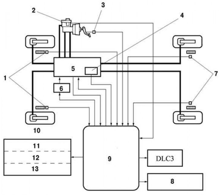
Pic. 6.4. Scheme of the circuit of the brake system of a Camry car: 1 - front wheel speed sensors; 2 - brake fluid level indicator; 3 – stoplight switch; 4 - pressure sensor of the main cylinder; 5 – the main brake cylinder assy
Braking is at its most effective when the grip of the tire on the road surface is at its maximum. During braking, the tire slides over the surface, and the circumferential speed of the wheel becomes less than the speed of the car.
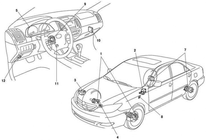
Pic. 6.5. Camry anti-lock braking system: 1 - front wheel speed sensors; 2 - sensor of deviation from the set course; 3 - control unit ABS / brake actuator; 4 - the main ABS relay; 5 - a combination of devices (pilot lamps)
Anti-lock braking system (pic. 6.5) limits the pressure generated in the hydraulic brake actuator so that the amount of slip is optimal. The operation of this system must be separate for each wheel. The system must immediately respond to every surface change (adhesion coefficient) and vehicle loads.
The anti-lock braking system prevents the wheels from locking during heavy braking, thereby reducing the braking distance. The grip force between the wheels and the road in this case is greater if the wheels continue to rotate during braking. Even with full braking, the car remains steerable. Speed sensors, one for each wheel, measure wheel speed. Based on the signals from the sensors, the electronic control unit calculates an average speed that approximately corresponds to the speed of the vehicle. By comparing the rotation speed of each individual wheel with the average calculated speed, the electronic unit determines the slip state of the individual wheel and thereby sets. which wheel is in the pre-lock state.
When one of the four wheel speed sensors transmits a locked wheel signal to the respective wheel, the ECU immediately sends a close signal to the respective inlet solenoid valve, which shuts off the brake fluid supply through the wheel brake line. In this case, the braking force remains constant. If slipping continues, the release valve opens and the pressure in the hydraulic system of that brake is reduced. The wheel does not brake, excess brake fluid returns to the reservoir. Once the wheel starts spinning again, the intake valve opens and the exhaust valve closes. The pressure in the circuit increases and the wheel brakes again.
The change between braking and free spinning cycles is very fast (several times per second) and continues until the vehicle stops or the brake pedal is released.
The process is repeated under hard braking separately for each wheel until the brake pedal is released.
The emergency system ensures that the ABS is turned off in case of any malfunction or low voltage in the car's on-board network (below 10 V). A faulty ABS does not affect the operation of the brakes.
The hydraulic drive consists of a hydraulic block, brake calipers and brake pipes. The hydraulic unit includes an electric pressure pump and solenoid valves.
Purpose of the TRC system
Based on the signals from the 4 wheel speed sensors, the ECU/TRC/ABS control unit determines wheel spin. In the event of a slip of a wheel, at the command of the control unit, the pressure of the brake fluid to the slipping wheel changes and the fuel supply to the engine is cut off. This unit also reduces the throttle opening angle. In the future, the throttle position is fixed in such a way as to provide the required engine power. When a wheel slips, the TRC system automatically applies brake fluid pressure to the wheel. The system warning light on the instrument panel flashes to alert the driver that the TRC system is operating. When the TRC system is on, the driver may experience some inertia. This phenomenon is indicative of a malfunction, as optimum traction takes precedence over other functions when the TRC system is operating. When driving in areas where the friction coefficient changes with the road surface, downshifting or depressing the accelerator pedal all the way down, the TRC system may temporarily turn on.
If a malfunction occurs in the throttle control system, the ECU/TRC is inoperative. At this point, only the ABS control system is working.
Purpose of the ECU system
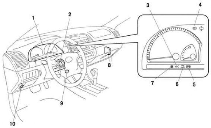
Pic. 6.6. Camry TRC/ECU system: 1 – a combination of devices; 2 - steering wheel angle sensor; 3 – a control lamp of protivozanosnoy system (VCS); 4 – a lamp of the alarm system of brake system; 5 – control lamp ABS
In addition to the operation of the ABS/TRC systems, the ECU system (pic. 6.6) through the steering angle sensor and the pressure sensor, it perceives the force exerted on the steering wheel and brakes. Using information from the yaw sensor/lateral acceleration sensor (G-sensor) and wheel speed sensors, the ECU evaluates driving behavior and improves stability by adjusting four-wheel braking force and engine power output.