
Attention! Operations to repair the hub and steering knuckle of the left and right front wheels are the same.
Removing
Remove the front wheel.
Using special tool 09930-00010, remove the front wheel hub nut.
Disconnect the front speed sensor.
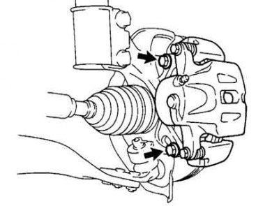
Pic. 3.139. Front caliper mounting bolts
Unscrew the 2 mounting bolts, disconnect the front disc brake caliper from the steering knuckle (pic. 3.139).
Remove the front disc.
Using special tool 09628-62011, disconnect the left tie rod.
Disconnect the No. 1 front suspension lower control arm.
Using a plastic mallet, separate the front wheel drive assembly from the front wheel hub.
Attention! Be careful not to damage the boot and ABS speed sensor rotor
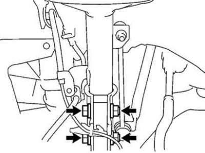
Pic. 3.140. Fastening of a rotary fist and a nave of a forward wheel
Unscrew 2 bolts, nuts and remove the steering knuckle with the front wheel hub (pic. 3.140).
Unscrew the cotter pin and nut.
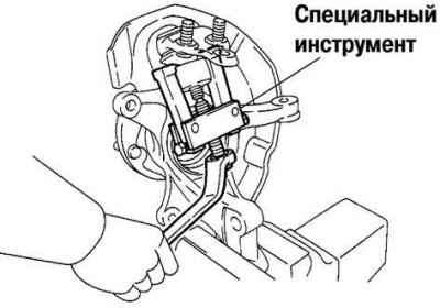
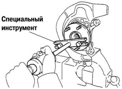
Pic. 3.141. Removing the lower ball joint of the front suspension
Using special tool 09628-62011, remove the front suspension lower ball joint (pic. 3.141).
Pic. 3.142. Removal of a lock ring of the internal hinge of the left drive shaft
Using a snap ring plier, remove the left drive shaft inner pivot snap ring (pic. 3.142).
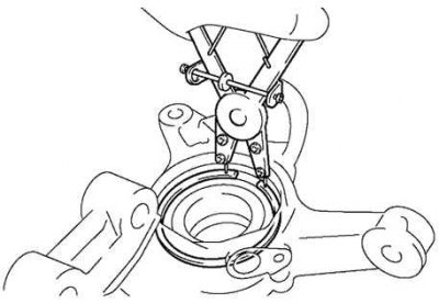
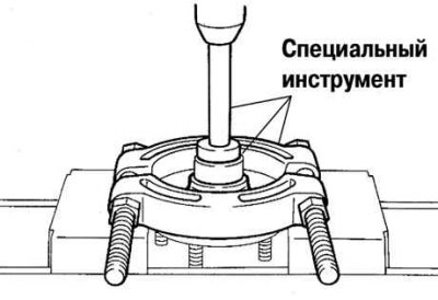
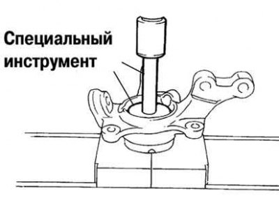
Pic. 3.143. Removing the front wheel hub
Using special tool 09520-00031, remove the front wheel hub (pic. 3.143).
Pic. 3.144. Removing the inner ring (outside) front wheel hubs
Using special tool 09950-00020 and a press, remove the inner ring (outside) front wheel hubs (pic. 3.144).
Using a Torx wrench (T30), remove the 4 bolts and remove the disc brake guard.
Place the inner ring (outside) on the front wheel bearing.
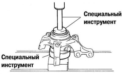
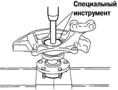
Pic. 3.145. Pressing the front wheel bearing into a special tool
Using special tool 09527-17011 and a press, press out the front wheel bearing until it stops in the special tool (pic. 3.145).
Pic. 3.146. Pressing out the front wheel bearing
Using a wrench for horizontal installation of the steering knuckle, install it on the stand, as shown in Figure 3.146.
Attention! Make sure the steering knuckle is horizontal.
Using special tool 09950-60010 and a press, press out the wheel bearing.
Installation
Using special tool 09950-60020 and a press, install a new front wheel bearing into the steering knuckle.
Install the disc brake guard and use a Torx wrench (T30), tighten 4 bolts.
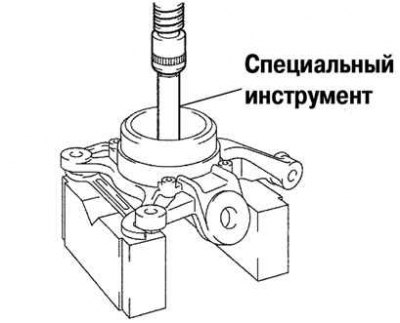
Pic. 3.147. Installing a new front wheel bearing
Pic. 3.148. Installing the front wheel hub
Using the special tool and a press, install the front wheel hub (pic. 3.148).
Using a snap ring installer, install a new front wheel hub hole snap ring.
Install the front suspension lower ball joint and tighten the nut.
Tightening torque: 123 Nm.
Install a new pin.
Attention! If the cotter pin holes do not line up, tighten the nut further up to 60°.
Install the 2 bolts, nuts and front hub assembly to the front suspension strut.
Tightening torque: 210 Nm.
Note. Insert the bolt from the front of the vehicle and tighten the nut.
Slide the front hub out, align the front wheel drive spline with the hole in the hub, and insert the front wheel drive into the hub.
Attention! Do not extend the front hub too far.
Attention! Be careful not to damage the outer hinge boot.
Attention! Be careful not to damage the ABS speed sensor rotor.
Install the No. 1 front suspension lower control arm.
Establish steering draft.
Install the front disc.
Install the disc brake caliper and secure it with two bolts to the steering knuckle.
Tightening torque: 106.9 Nm.
Install the front wheel hub nut.
Disconnect the disc brake caliper and check the hub bearing clearance and other checks described above in subsection «Vehicle check».
Install the final disc brake caliper onto the steering knuckle and secure it with 2 bolts.
Install the front speed sensor.
Install the front wheel.
Tightening torque: 103 Nm.
Check and adjust the angles of the front wheels.
Check ABS speed sensor signal.