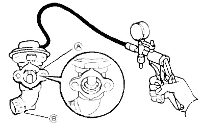
Apply vacuum to the upper chamber of the valve and check for recirculation between A and B.
Meaning:
- less than 100 mm Hg - no
- over 200 mm. Hg - yes
2. Checking the electro-pneumatic vacuum control valve.
A) Check resistance between valve leads.
- Resistance (at 20°C) — 10-12 Ohm at 20°С
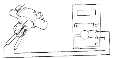
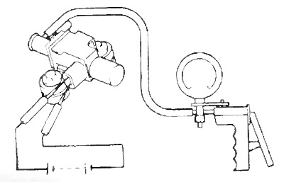
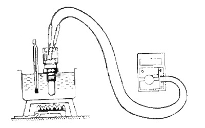
b) Apply vacuum to the valve as shown in the figure.
Vacuum 350 mmHg and higher. If the vacuum decreases, but the arrow remains at around 350 mm Hg. and above - the valve is working.
V) Checking work.
Apply 6V to the valve terminals.
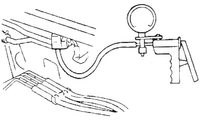
Apply vacuum as shown in the figure above.
The discharge should not increase.
3. Checking the control lever position sensor.
A) Measure resistance between leads "VC" and ''E2".
- Resistance 1.84 - 3.42 Ohm
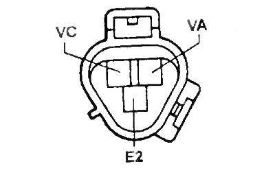
Make sure there is a drop in resistance between the terminals "VA" And "E2" with the accelerator pedal depressed and not depressed.
When you press the accelerator pedal, the resistance decreases.
- Pedal - resistance
- Pressed - 1.38-7.57 kOhm
- Not pressed - 0.26 - 5.66 kOhm
4. Checking the absolute pressure sensor in the intake manifold.
A) Turn on the ignition.
b) Measure voltage between terminals "VC" And "ET" electronic control unit (with plug connected).
- Voltage - 4.5-5.5 V
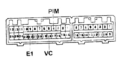
V) Apply pressure to the sensor and measure the voltage between the terminals "PIM" And "ET" electronic control unit.
pressure voltage
- - 300 mm Hg - 0.2 -0.8 V
- 0 (atmospheric) - 1.3 -1.9 V
- + 0.7 bar (1275 mmHg) - 3.2 - 3.8 V
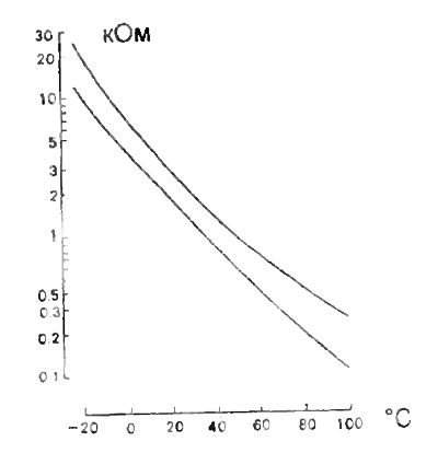
5. Coolant temperature sensor.
Measure the resistance between the sensor leads.
Resistance
- at 20°0 - 2-3 kOhm
- at 80°0 - 0.2-0.3 kOhm
 |  |
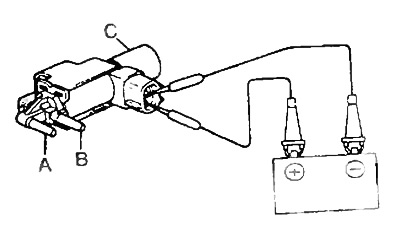
6. Checking the electro-pneumatic valve of the exhaust gas recirculation system and the electro-pneumatic valve for increasing the idle speed when the air conditioner and heater are turned on.
Apply battery voltage to the valve terminals and check the passage of air between the valve outlets.
The voltage is:
- A - B - air passes
- B - C - air does not pass
No voltage:
- A - B - air does not pass
- B - C - air passes
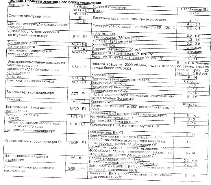
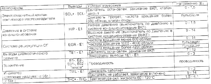
7. Checking the electronic control unit of the toxicity reduction system.
A) Measure the voltage between the terminals of the electronic unit as indicated in the table "Checking the electronic control unit".
b) Using an oscilloscope, verify that there are pulses between the pins.
Note:
- Measure from the back of the harness connector.
- Before measuring voltages, check the power (with the ignition on 10 - 14 V) and check grounding (with the ignition off "Earth"- motor-case resistance less than 5 ohm.
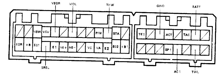
Conclusions of the electronic control unit (until 1995)
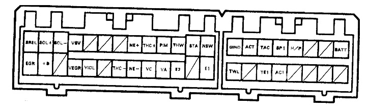
Conclusions of the electronic control unit (since 1995)
Table. Checking the electronic control unit.