
2. Remove the air filter cover with air duct.
3. Disconnect the accelerator cable.
4. Remove the four clips and disconnect the wiring harness.
5. Disconnect the crankcase ventilation hose.
6. Disconnect vacuum hoses in the places shown in drawing.
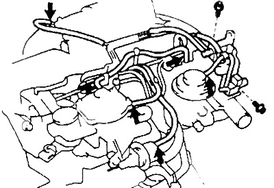
7. Disconnect vacuum control solenoid connectors (EVRV) and electropneumatic valve of the exhaust gas recirculation system.
Removal and installation of a head of the block of cylinders in gathering (ZS-T)
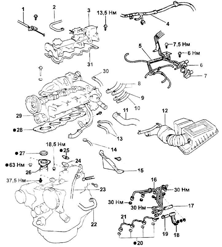
1 - accelerator cable,
2 - vacuum hose,
3 - block head cover assembly with a vacuum pump,
4 - wiring harness,
5 - vacuum hoses,
6 - vacuum control solenoid valve (EVRV) exhaust gas recirculation systems,
7 - electropneumatic valve of the exhaust gas recirculation system,
8 - heater hoses,
9 - fuel supply hose,
10 - fuel return hose,
11 - cooling system hose (radiator inlet hose),
12 - air filter cover with air duct,
13 - fuel hoses,
14 - temperature sensor connector,
15 - cover No. 3 of the timing belt,
16 - high pressure fuel pipes,
17 - clamp No. 2 of the high pressure fuel pipe,
18 - fuel pump connector bracket,
19 - fuel return hose,
20 - gasket,
21 - drainage tube,
22 - coolant bypass hose,
23 - oil dipstick guide,
24 -, 25-, 27-, 28-, 31 - gasket,
26 - a reception pipe of the exhaust system,
29 - cylinder head assembly,
30 - hose No. 1 for cooling the turbocharger.
Turn away three bolts and remove the specified valves.
Note: Do not disconnect vacuum hoses from valves.
8. Turn away three bolts and move aside a vacuum tube aside.
Note: Do not disconnect the vacuum hose.
9 Remove the vacuum pump head cover.
A) Remove the cover cap No. 2 of the timing belt.
b) Turn the crankshaft clockwise until the mark on the camshaft pulley is at the bottom.
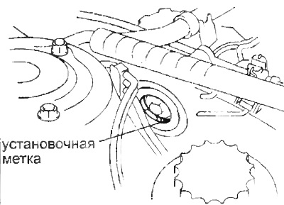
In this position, the vacuum pump piston is at BDC and the spring compression becomes the smallest.
V) Unscrew the two bolts of the cover No. 2 of the timing belt.
G) Loosen the wiring harness bolt.
d) Unscrew 10 bolts and remove the cover with the pump.
10. Remove the timing belt (see relevant section).
11. Disconnect the two coolant bypass hoses. Turn away a bolt, move a collar and disconnect a hose of a supply of a cooling liquid.
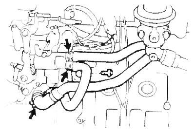
12. Disconnect the radiator inlet hose.
13. Disconnect the wiring harness from the glow plug connector.
14. Remove the protective cover No. 3 of the timing belt.
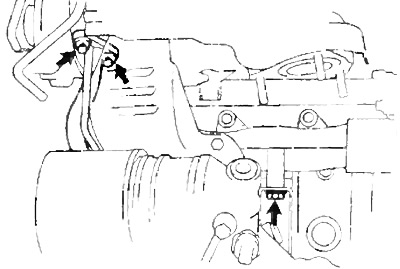
15. Disconnect a socket of the gauge indicator of level of a cooling liquid.
16. Remove the clamp, then remove the dipstick guide.
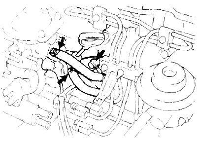
17. Disconnect the fuel hose.
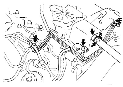
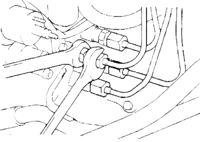
18. Remove the high pressure fuel pipes.
A) Unscrew 3 nuts, remove the injection pump connector mounting bracket and clamp No. 2 of the high pressure fuel pipe.
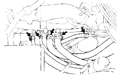
b) Unscrew the four fastening nuts shown in the figure and disconnect the fuel pipes from the injectors.
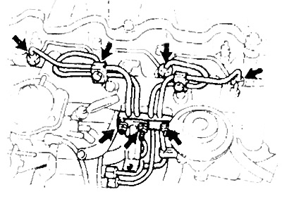
V) As shown in the figure, unscrew the four nuts and disconnect the fuel pipes from the injection pump.
19. Remove the drain tube.
20. Disconnect fuel hoses and heater hoses.
21. Remove the turbocharger cooling hose No. 1.
22. Turn away 3 nuts and remove a reception pipe of system of release.
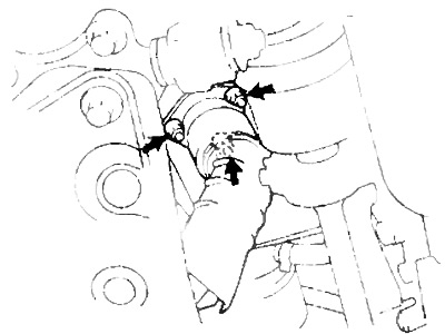
23. Turn away a bolt and disconnect a final collector and a rack.
Remove the two nuts and disconnect the oil pipe from the turbocharger.
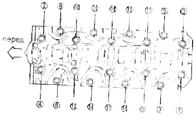
24. Removing the cylinder head.
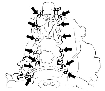
A) Loosen the 18 head bolts in the sequence shown in the figure, then unscrew them completely and remove them together with the washers.
b) Remove the block head.
V) Remove the head gasket.