
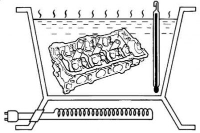
Pic. 2.267. Heating the cylinder head in a water bath
Gradually heat the cylinder head in a water bath to a temperature of 80-100°C (pic. 2.267).
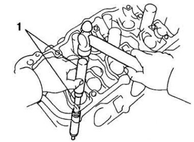
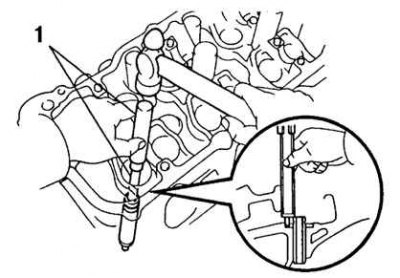
Pic. 2.268. Pressing out the guide bushing: 1 - drift
Using a drift and hammer, press out the guide bushing (pic. 2.268).
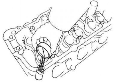
Pic. 2.269. Bore diameter measurement
Using a inside gauge, measure the diameter of the bore for the guide bushing in the cylinder head housing (pic. 2.269).
Select new valve guide OD size (standard or repair +0.05 mm).
If the diameter of the hole for the guide in the head body exceeds 10.313 mm, then bore the hole for the guide sleeve to the repair (+0.05 mm) diameter 10.345–10.363 mm.
If the diameter of the hole for the guide in the block head housing exceeds the repair size, then replace the cylinder head. Select the inlet and outlet valve bushings depending on the guide hole diameters.
Use a standard bushing if the guide hole diameter is 10.295–10.313 mm.
Use repair (+0.05 mm) bushing if the guide hole diameter is 10.345–10.363 mm.
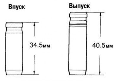
Pic. 2.270. Intake and exhaust valve guides
Note. Inlet and exhaust valve guides vary in length (pic. 2.270).
Guide bushing length:
- intake valves - 34.5 mm;
- exhaust valves - 40.5 mm.
Heat the cylinder head in a water bath to a temperature of 80-100°C (see fig. 2.267).
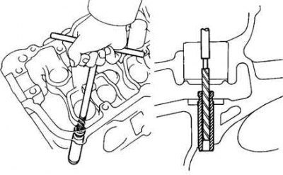
Pic. 2.271. Installing a new guide bushing: 1 - drift
Using a drift and hammer, install the new valve guide so that it protrudes from the block head by the appropriate amount (pic. 2.271).
Guide bush protrusion:
- intake valve - 11.5–11.3 mm;
- exhaust valve - 8.9–9.3 mm.
Pic. 2.272. Reaming the inner hole of the rail
Using a 5.5 mm reamer, ream the inner hole of the guide to provide the nominal clearance between the guide and valve stem (pic. 2.272).