
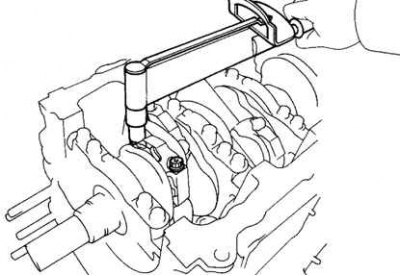
Pic. 2.319. Unscrewing the connecting rod bottom cap bolts
Check the alignment of the marks on the connecting rod and the connecting rod cap to ensure proper assembly in the future. If there are no marks, apply them to the caps and connecting rods with a core. Loosen the two connecting rod bottom cap bolts (pic. 2.319).
Using the connecting rod cap bolts, remove the bottom cap by rocking it from side to side.
Install a plastic gauge to measure the clearances in the plain bearings across the crankpin.
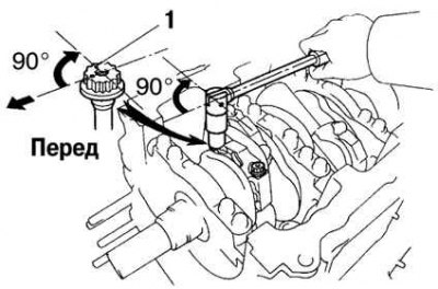
Pic. 2.320. Connecting rod bottom cover installation
Install the connecting rod lower cover by aligning the match marks. Tighten the bolts with a tightening torque of 25 Nm by turning their heads 90° (pic. 2.320).
Note. Do not rotate the crankshaft.
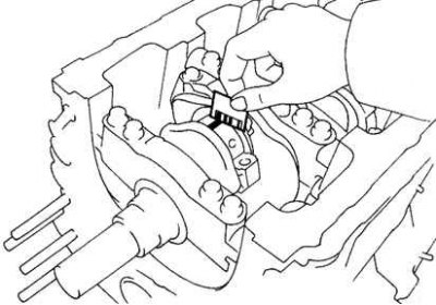
Pic. 2.321. Removing the plastic gauge
Remove the bottom cover of the connecting rod by unscrewing the bolts. Measure the width of the flattened plastic gauge at its widest point and determine the connecting rod bearing clearance (pic. 2.321).
Connecting rod bearing clearance:
- standard - 0.038–0.064 mm;
- maximum - 0.080 mm.
If the clearance is greater than the maximum, replace the bearings. Regrind or replace crankshaft if necessary.
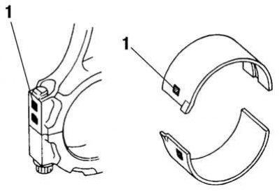
Pic. 2.322. Location of number markings: 1 - marking with number
Note. When replacing nominal size bearings, use bearings of the same size group as indicated on the bottom cap or connecting rod. There are size groups of liners, indicated «1», «2», «3», «4» (pic. 2.322).
Nominal liner wall thickness (in the center):
- label «1» - 1.484–1.487 mm;
- label «2» - 1.487–1.490 mm;
- label «3» - 1.490–1.493 mm;
- label «4» - 1.493–1.496 mm.
Remove any remaining plastic gauge from the working surfaces of the neck and insert.