
Four-cylinder exhaust emission control system
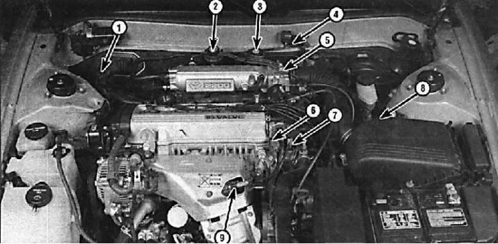
1 - diagnostic connector; 2 - EGR vacuum modulator; 3 - EGR valve; 4 - MAP-sensor; 5-TPF (behind throttle body); 6 - coolant temperature sensor; 7 - ignition distributor; 8 - ignition block (behind the air filter); 9 - oxygen sensor
Six-cylinder engine emission control system
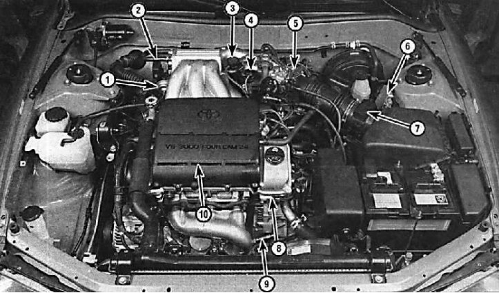
1 - air control valve; 2 - diagnostic connector; 3 - EGR vacuum modulator; 4 - EGR valve; 5-TPS (behind throttle body); 6 - ignition block; 7 - NAF-sensor; 8 - camshaft position sensor; 9 – oxygen sensor; 10 - ignition coils (located under the casing)
Typical diagram of the location of the vacuum hoses on a four-cylinder engine
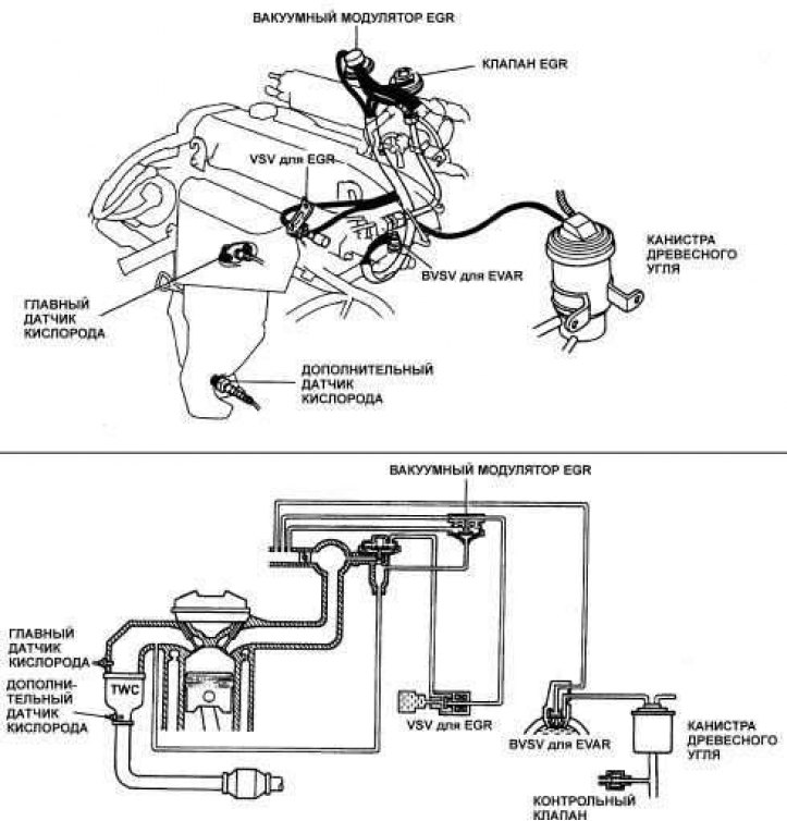
Typical vacuum hose diagram on a 3VZ-FE V6 engine
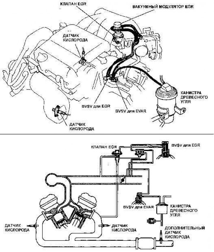
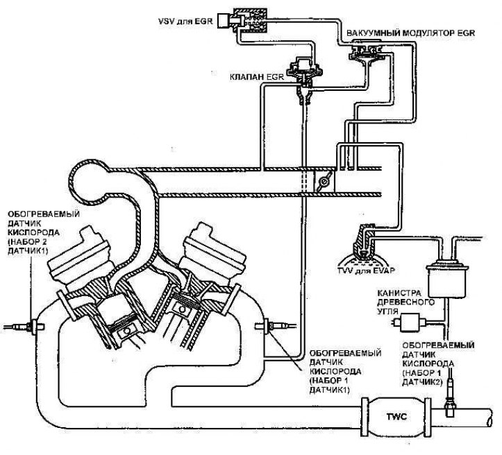
Schematic arrangement of vacuum hoses on the 1MZ-FE V6 engine
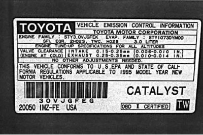
Identification plate with data on the emission control system, idle speed and ignition timing
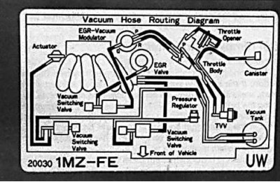
Identification plate with schematic arrangement of vacuum hoses
In order to reduce atmospheric pollution from incompletely burned hydrocarbons and evaporating gases and create optimal conditions for engine operation, the following exhaust gas toxicity reduction systems are used:
- crankcase ventilation system;
- vapor recovery system (EVAP);
- waste gas re-burning system (EGR);
- catalyst (TWC);
- electronic fuel injection system (EFI);
- induction air supply system.