



Contents: V6 engines 1992 and 1993 ↓ V6 engines since 1994 ↓ Four-cylinder engines ↓ Six-cylinder engines 1992 and 1993 ↓ Six-cylinder engines since 1994 ↓
Caution! Use only a pointer voltmeter, as it is necessary to observe the oscillation of the pointer.
One or two oxygen sensors are installed on cars. On models with two sensors, the main oxygen sensor is installed before the catalytic converter and monitors the composition of the exhaust gases that have not been purified by the catalytic converter. The additional oxygen sensor monitors the composition of the exhaust gases after they have passed through the catalytic converter. Depending on the oxygen content in the exhaust gases, the sensor induces a voltage of 0.1 V (high oxygen, lean mixture) up to 0.9 V (low oxygen, rich mixture). Based on this data, the ECM changes the opening time of the fuel injectors and changes the fuel ratio in the fuel mixture.
The oxygen sensor does not induce any voltage when the sensor temperature is less than 315°C.
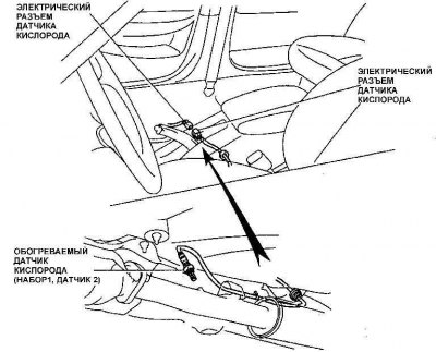
To access the rear oxygen sensor connectors, the front seat must be removed.
Checking the performance of the oxygen sensor on six-cylinder engines
 | 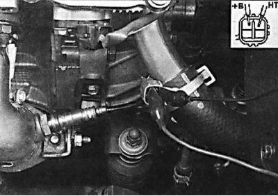 |
1. To test the oxygen sensor, disconnect the electrical connector from the sensor and connect an ohmmeter to the +B and NT terminals of the sensor connector. The resistance of the sensor should be between 11 and 17 ohms. On four-cylinder models, the oxygen sensor is connected with a single wire. On six-cylinder models with an oxygen sensor heater, the sensor is connected with a four-pin connector. Later four-cylinder models have two oxygen sensors, and six-cylinder models have three oxygen sensors. Bank 1 Sensor 1 and Bank 2 Sensor 1 are located before the catalytic converter, and Bank 1 and Sensor 2 are located after the catalytic converter. On six-cylinder models, the front seat must be removed to access the rear oxygen sensor electrical connector.
2. Check the condition of the oxygen sensor heater electrical circuit. When the ignition is turned on, 12 V should be present at the connector terminals (See Table "V6 Engines 1992 and 1993", "V6 Engines Since 1994").
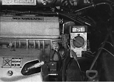
3. Check the voltage induced by the oxygen sensor. Connect one lead of the millivoltmeter to the electrical connector of the oxygen sensor and connect the other lead to ground. Check the voltage produced by the oxygen sensor at the terminals (See the table "Four-Cylinder Engines", "Six-Cylinder Engines 1992 and 1993", "Six-Cylinder Engines Since 1994").
4. The signal value induced by the oxygen sensor on a cold engine is from 0.1 to 0.2 V, and after the engine warms up it fluctuates from 0.1 to 0.9 V.
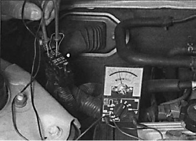
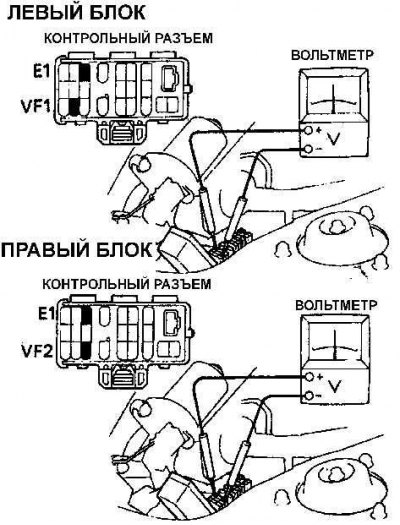
5. On 1992 and 1993 models, warm up the oxygen sensor to operating temperature and connect a voltmeter to terminals VF1 and E1 of the test connector.
6. On six-cylinder engines, connect a pointer voltmeter to terminals VF1 and E1 and terminals VF2 and E1 to check the functionality of the oxygen sensor (See Fig. Checking the performance of the oxygen sensor on six-cylinder engines).
7. Start the engine and increase its speed to 2500 rpm for 2 minutes and then short-circuit the contacts TE1 and E1 of the control connector with an additional wire. Check that the voltmeter needle fluctuates 8 times in 10 seconds.
 |  |
[View the full text on the portal ToyotaMan.ru]
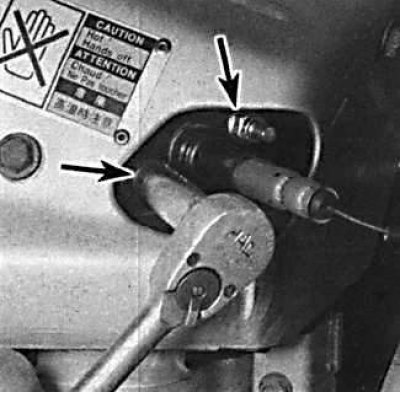
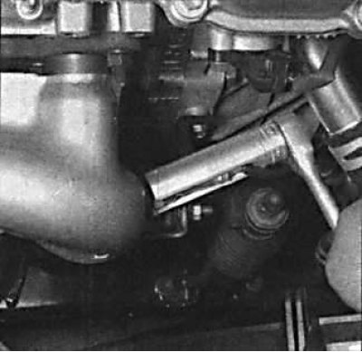
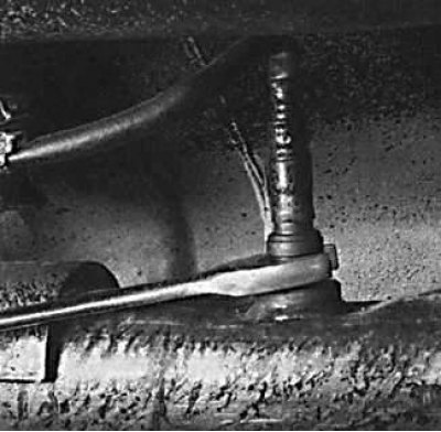
8. To replace the oxygen sensor, remove the ground wire, lift the vehicle, disconnect the connector from the sensor and unscrew the oxygen sensor.
V6 engines 1992 and 1993
| additional | black/orange wire (+) |
| oxygen sensor | brown wire (-) |
| main #1 | not used |
| main #2 | not used |
V6 engines since 1994
| block 1 sensor 1 | black/orange wire (+) brown wire (-) |
| block 2 sensor 1 | black/orange wire (+) brown wire (-) |
| block 1 sensor 2 | black/orange wire (+) brown wire (-) |
Four-cylinder engines
| main oxygen sensor | white wire |
| additional oxygen sensor | red/blue wire |
Six-cylinder engines 1992 and 1993
| main #1 | white wire |
| main #2 | red/blue wire |
| additional oxygen sensor | white wire |
Six-cylinder engines since 1994
| block 1 sensor 1 | white wire |
| block 2 sensor 1 | red/blue wire |
| block 1 sensor 2 | black wire |