
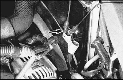
Location of coolant temperature sensor N1 (4-cylinder models)
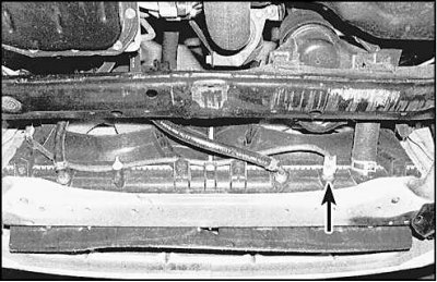
Coolant temperature sensor N1 (indicated by an arrow) located at the back of the radiator.
Location of coolant temperature sensor N1 (6-cylinder models)
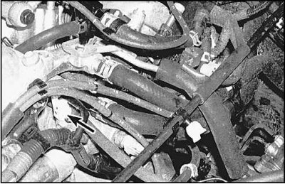
On 6-cylinder models, coolant temperature sensor (indicated by an arrow) located on the thermostat housing.
N1 Main Engine and Cooling Fan Relay - Model Avalon
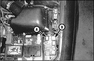
A - the main relay of the engine
B - cooling fan relay
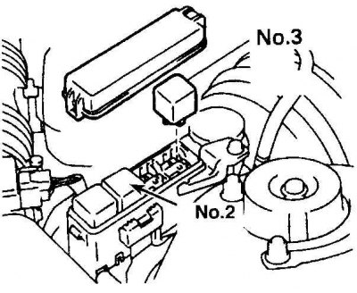
Cooling Fan Relay Box - Model Avalon
Examination
1. If the cooling fan does not turn off when the engine is cold, disconnect the wire from the fan temperature sensor and short the wire with a jumper wire. If the fan stops, replace the sensor.
2. Check N1 fan sensor with an ohmmeter. When the engine is cold, the sensor circuit should be closed. When the engine is warm, the sensor circuit should be open.
3. Check the N2 sensor in the same way. The circuit is open if the temperature is below 84°C and the circuit is closed if the temperature is over 90°C. Replace sensor if necessary.
4. If the fan motor is faulty, first check the fan fuse located under the hood in the relay and fuse box. Disconnect the wire from the fan motor and connect the fan contacts with adapters to the battery terminals. If the fan still does not work, replace the motor.
5. If the sensors are working and the motor has passed the test, then you need to check the fan relay, wiring and electronic control unit.
Relay test
1. The relay box is located on the left side in the engine compartment. If the car is equipped with an air conditioning system, then the relay block has an N2 relay for the second fan, and in some models there is an N3 relay (see fig. Cooling Fan Relay Box - Model Avalon).
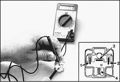
2. Remove relay N1 and test it with an ohmmeter. The circuit must be closed between pins 1 and 2 (85 and 86 on Bosch relays) and between pins 3 and 4 (30 and 87a 86 on a Bosch relay). When battery voltage is applied to pins 1 and 2, the circuit between pins 3 and 4 should be open.
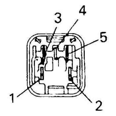
3. If the relay is functioning properly, remove the main engine relay and test it. Circuit is closed between pins 3 and 5 and pins 2 and 4. Circuit is open between pins 1 and 2. When voltage is applied to pins 3 and 5, circuit 1-2 is closed and circuit 2-4 is open. If all relays work properly, but the fan still does not function, contact a specialist.
Replacement
1. Disconnect the negative battery cable.
2. Disconnect the wire from the fan motor. Disconnect the wires attached to the fan shroud.
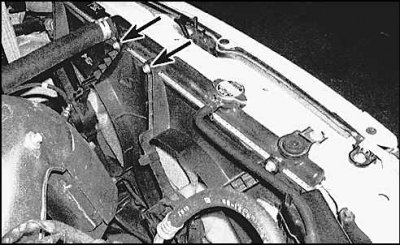
3. Remove the bolts (indicated by arrows) and remove the fan shroud from the engine compartment.
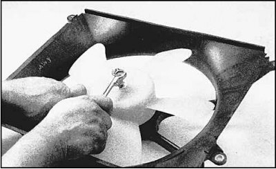
4. Loosen the fan nut and remove the fan from the motor.
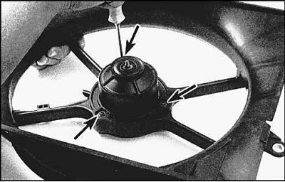
5. Unscrew bolts and remove the electric motor.
6. Installation is carried out in the reverse order of removal.