
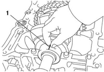
Pic. 2.120. Measurement of clearances in plain bearings: 1 - plastic gauge
Clean each main journal and bearings. Check the surface of each main journal and bearings for pitting and scratches. If the neck or insert is damaged, replace the inserts. Regrind or replace crankshaft if necessary. Install the crankshaft in the bed of the cylinder block. Place a plastic bearing clearance gauge on each journal (pic. 2.120).
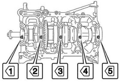
Pic. 2.121. Numbering of main bearing caps
Install the main bearing caps (pic. 2.121).
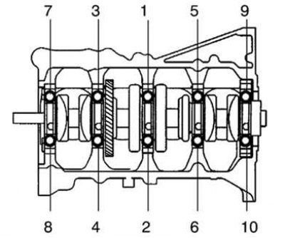
Pic. 2.122. The order of tightening the bolts of the main bearing caps
Tighten the mounting bolts in the order shown in Figure 2.122.
Remove the main bearing caps. Measure the maximum width of the flattened gauge wire to determine the radial clearance.
- The standard gap is 0.017–0.040 mm.
- Limit clearance - 0.050 mm.
If the clearance is greater than the maximum, replace the bearings. Replace crankshaft if necessary.
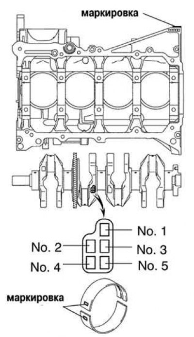
Pic. 2.123. Numbering of liners of main bearings
When replacing nominal size inserts, inserts of the same size group must be used. There are several standard size groups of liners, indicated «1», «2», «3», «4». The size group of the liner is determined based on the sum of the size groups indicated on the cylinder block and crankshaft (pic. 2.123).
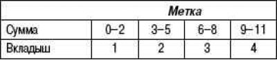
Example: label «4» on the cylinder block + mark «3» on crankshaft = sum «7» (required insert #3).
Remove the remnants of the caliber from the working surfaces of the main journal and the liner.
Remove the crankshaft.
With the crankshaft raised, remove the upper main bearing shells and the upper thrust washers from the cylinder block.