
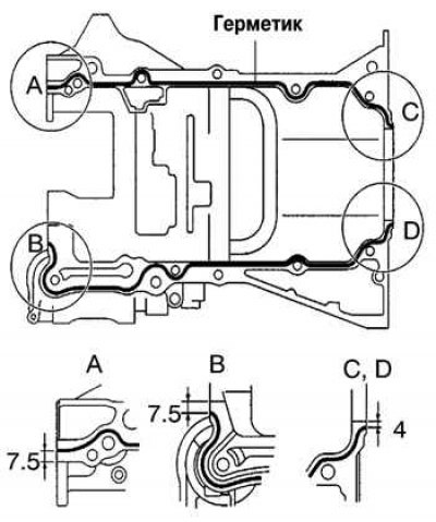
Pic. 2.135. Sealing locations
Remove old sealant. Be careful not to damage the contact surfaces. Using a blade and scraper, remove old sealant from the contact surfaces and sealant recesses. Thoroughly clean all components before installation. Using a non-residue solvent, clean surfaces before applying sealant. Apply fresh sealant to the crankcase, as shown in Figure 2.135.
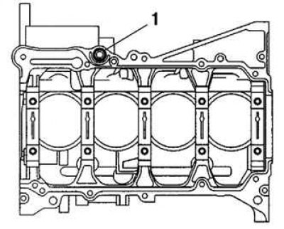
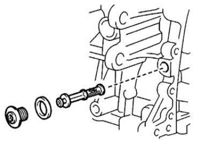
Pic. 2.136. Lock Seal Location: 1 - retaining seal
Install a new O-ring (pic. 2.136).
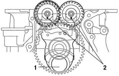
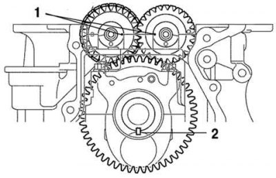
Pic. 2.137. Installation marks for balancer shafts and crankpin: 1 - neck No. 1; 2 - labels
Orient the labels on the balancer shafts and connecting rod neck No. 1, as shown in Figure 2.137.
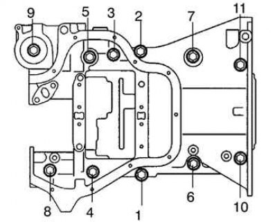
Pic. 2.138. The procedure for tightening the crankcase bolts
Install crankcase. Evenly, in several passes, tighten the crankcase mounting bolts in the sequence shown in Figure 2.138 with a tightening torque of 33 Nm.
Pic. 2.139. Installation marks for balancer shafts and keys: 1 - marks; 2 - key
Check the alignment of labels, as shown in Figure 2.139.
Pic. 2.140. Installing the VVT-i oil filter
Install the plug by applying thread sealant and tighten to 26 Nm. Install the VVT-i oil filter and tighten to 30 Nm (pic. 2.140).
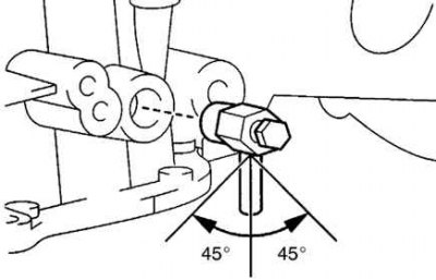
Pic. 2.141. Drain valve installation
Tighten the drain cock with a tightening torque of 25 Nm, applying sealant to 2-3 threads. After tightening the tap to the required torque, turn it clockwise until the drain hole is at the bottom (pic. 2.141).
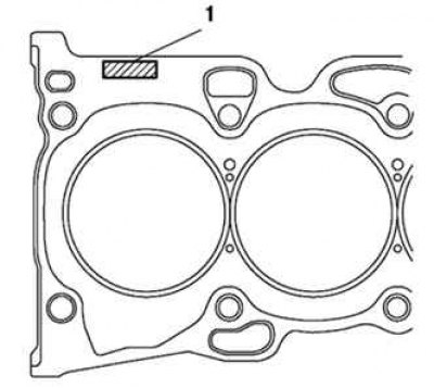
Pic. 2.142. Cylinder Head Gasket: 1 - number
Install the oil cooler fitting (oil cooler models). Install the cylinder head gasket (pic. 2.142).