
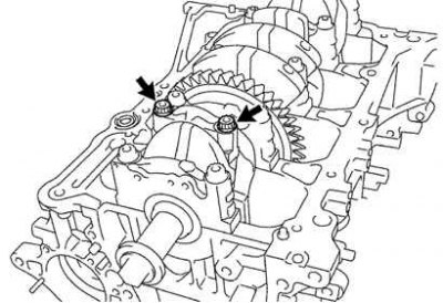
Pic. 2.96. Connecting rod cap bolts
Check alignment of marks on connecting rod and connecting rod cap to ensure correct reassembly. If there are no marks, apply them to the caps and connecting rods with a core. Loosen the connecting rod cap bolts (pic. 2.96).
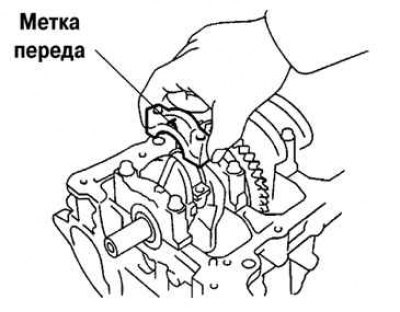
Pic. 2.97. Removing the connecting rod cap
Turn away bolts of fastening of a cover of a rod. Remove the connecting rod cap by swinging it by the connecting rod bolts (pic. 2.97).
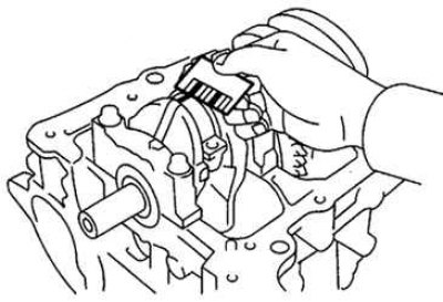
Pic. 2.98. Installing a plastic gauge
Check the condition of the working surfaces of the connecting rod journal and liners. If there are scratches or nicks, replace the eartips. Regrind journals or replace crankshaft if necessary. Install a plastic gauge to measure the clearances in the plain bearings across the crankpin (pic. 2.98).
Install the connecting rod cap, aligning the alignment marks, and tighten the fastening nuts (see fig. 2.97). Remove the connecting rod lower cover by unscrewing the nuts. Measure the maximum width of the flattened gauge wire, using it to determine the radial play of the connecting rod bearing.
The standard play of the connecting rod bearing is 0.024–0.048 mm.
The limit play of the connecting rod bearing is 0.080 mm.
If the clearance is greater than the maximum, replace the bearings. Replace crankshaft if necessary.