
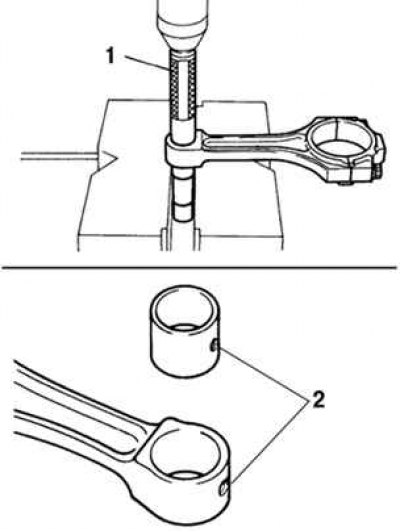
Pic. 2.337. Pressing the bushing out of the upper head of the connecting rod: 1 - special tool; 2 - oil hole
Using a drift and a press, press the bushing out of the connecting rod head. Align the lubrication holes of the new bushing and connecting rod and press the bushing (pic. 2.337).
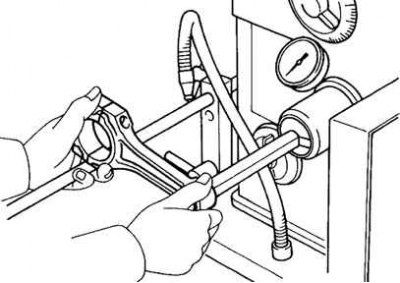
Pic. 2.338. Grinding the bushing to obtain the nominal clearance
Using a special tool and a press, press in the bushing. Measure the piston pin oil clearance and, if necessary, grind or regrind a new bushing until the nominal clearance is obtained (pic. 2.338).
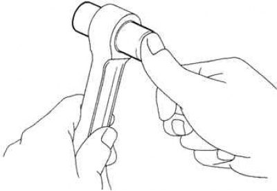
Pic. 2.339. Piston pin installation
Apply engine oil to the piston pin and press on it, as shown in Figure 2.339.
Make sure the piston pin moves (at normal room temperature)
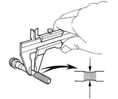
Pic. 2.340. Bolt Neck Measurement
Measure the outer diameter of the thin part of the bolts with a caliper. If this part is difficult to detect visually, then measure at a distance of 20 mm from the bolt head, as shown in Figure 2.340.
Bolt outer diameter:
- standard - 7.2–7.3 mm;
- minimum - 7.0 mm.
If the diameter is less than acceptable, replace the bolt.