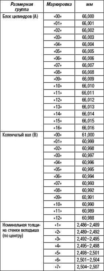
Pic. 2.345. Measurement planes for connecting rod and main journals
Micrometer measure the diameter of each connecting rod and main journal in two mutually perpendicular planes, as shown in Figure 2.345.
Main journal diameter: standard - 60.988-61.000 mm.
Crankpin diameter: standard - 52.992-53.000 mm.
If the diameters are outside the specified limits, check the oil clearances. Regrind or replace crankshaft if necessary.
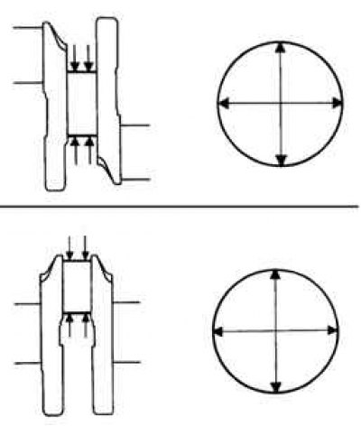
Pic. 2.346. Installation of the lower thrust half rings of bearing No. 2
Clean each main journal and bearings. Check the surface of each main journal and bearings for pitting and scratches. If the neck or insert is damaged, replace the inserts. Regrind or replace crankshaft if necessary. Establish the bottom persistent half rings on a cover of the radical bearing No. 2, having oriented greasing grooves outwards, as is shown in drawing 2.346.
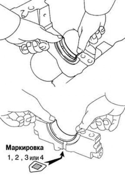
Pic. 2.347. Installing the plastic gauge: 1 - caliber
Lay a cranked shaft in the block of cylinders. Place a plastic bearing clearance gauge on each journal (pic. 2.347).
Pic. 2.348. Installation of main bearings
Install bearings (pic. 2.348).
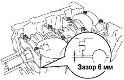
Pic. 2.349. Gap between main bearing cap and cylinder block connector
Apply a coat of engine oil to the threads and under the bolt heads (with 12-point head). Temporarily install the eight bearing cap bolts. Using the bolts as guides, insert the bearing cap so that the gap between it and the cylinder block connector is less than 6 mm (pic. 2.349).
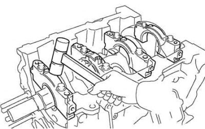
Pic. 2.350. Additive for main bearing caps
Using a plastic-faced hammer, knock down the bearing caps so that they fit snugly (pic. 2.350).
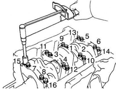
Pic. 2.351. The order of tightening the bolts of the main bearing caps
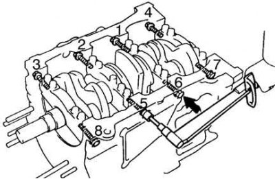
Apply a light coat of engine oil to the threads and under the heads of the main bearing cap bolts (with 12-point head) and install them. Install and evenly tighten the sixteen bolts of the main bearing caps in several passes in the sequence shown in Figure 2.351.
If any bolt is not tightened to the correct torque, replace the bolt.
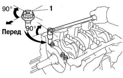
Pic. 2.352. The correct position of the mark when tightening the cylinder head bolts
Apply paint marks to the front of the cylinder head bolts. Tighten the cylinder head bolts 90°in the above sequence. Check that the inked mark is 90°from the original position (pic. 2.352).
Pic. 2.353. The sequence of tightening the bolts of the main bearing caps
Install the old sealing washers on the main bearing cap pinch bolts. Install and evenly tighten the coupling bolts of the main bearing caps in several passes with a tightening torque of 27 Nm in the sequence shown in Figure 2.353.
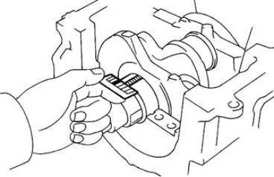
Pic. 2.354. Plastic gauge showing the value of the radial oil clearance
Remove the main bearing caps as above. Measure the maximum width of the flattened plastic gauge to determine the radial oil clearance (pic. 2.354).
Oil clearance:
- main bearings No. 1 and No. 4 -
- standard - 0.014–0.036 mm;
- maximum - 0.05 mm;
- main bearings No. 2 and No. 3 -
- standard - 0.026–0.048 mm;
- maximum - 0.06 mm.
If the oil clearance is greater than the maximum, replace the bearings. Regrind or replace crankshaft if necessary.
When replacing nominal size inserts, inserts of the same size group must be used. If the bearing size group number cannot be determined, select the correct bearing from the table by adding the cylinder block size group number to the crankshaft size group number.
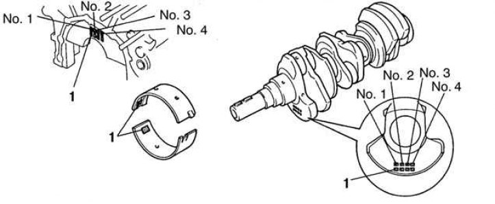
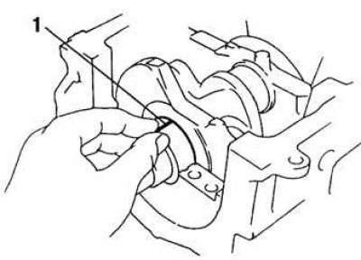
Pic. 2.355. Location of number markings: 1 - number markings
There are five standard size groups for earbuds, labeled «3», «4», «5», «6» and «7» (necks No. 1 and No. 4), «1», «2», «3», «4», «5» (necks No. 2 and No. 3) respectively (pic. 2.355).
Table 2.33. Dimensional groups of liners of main bearings