
Removing
Note: Installation is in reverse order of removal. After installation, check the alignment of the front wheels and the operation of the speed sensors (ABS).
1. Jack up the car, remove the front wheel.
- Tightening torque - 105 Nm
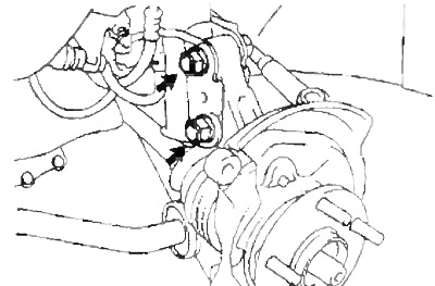
2. Turn away a bolt and remove the gauge of frequency of rotation (ABS).
- Tightening torque - 8 Nm
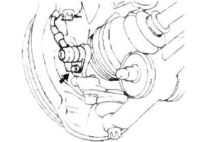
3. Check bearing end play and hub runout.
A) Turn away two bolts, remove a support and a brake disk.
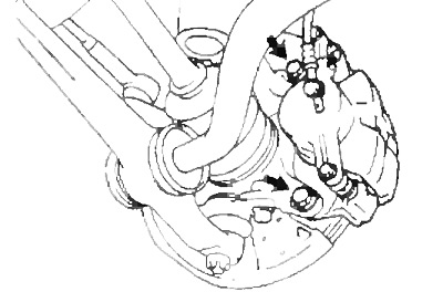
b) Hang the caliper on the wire.
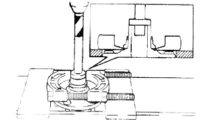
V) Using a dial gauge, check bearing end play and hub runout.
- Maximum clearance - 0.05 mm
- Maximum runout - 0.03 mm
 |  |
If the gap and (or) runout exceeds the specified value, replace the bearing.
G) Install the brake disc, caliper and tighten the two bolts.
- Tightening torque - 109 Nm
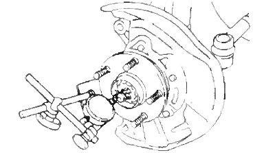
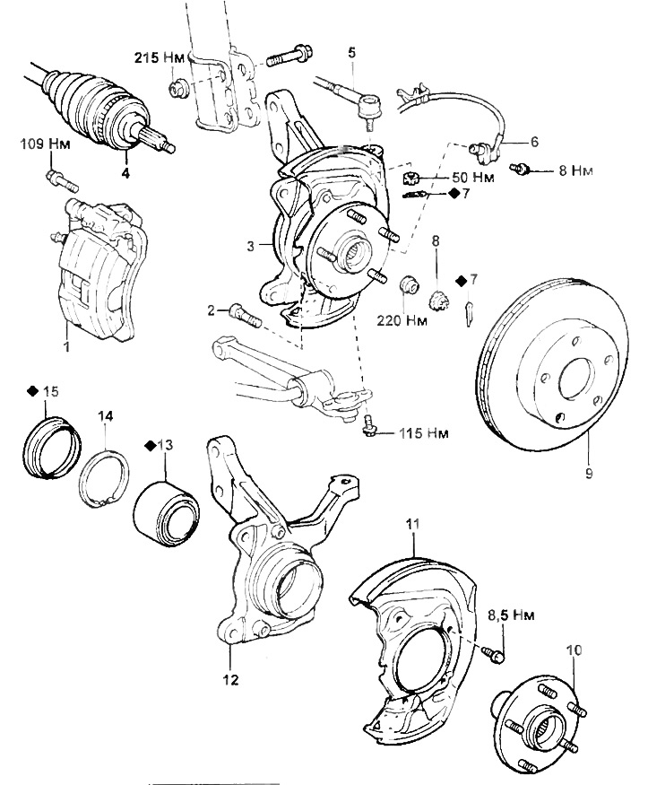
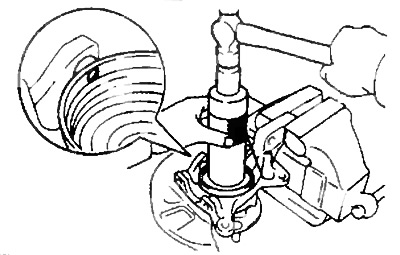
4. Loosen the locknut.
A) Remove cotter pin and locknut cap.
b) Loosen the locknut with the brake pedal depressed and unscrew it.
- Tightening torque - 220 Nm
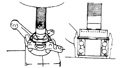
Hub and steering knuckle.
1 - support,
2 - hub bolt,
3 - hub and steering knuckle,
4 - front drive shaft,
5 - tie rod end,
6 - speed sensor (ABS),
7 - cotter pin,
8 - locknut cap,
9 - brake disc,
10 - hub,
11 - mudguard,
12 - steering knuckle,
13 - bearing,
14 - retaining ring,
15 - anther.
V) Remove the caliper and brake disc.
- Tightening torque - 109 Nm
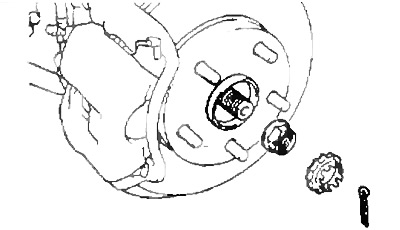
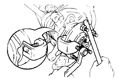
5. Turn away bolts of fastening of a spherical support to a fist.
- Tightening torque - 115 Nm
6. Disconnect the tie rod end from the steering knuckle.
A) Remove the cotter pin and unscrew the nut.
- Tightening torque - 50 Nm
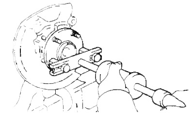
b) Using a puller, disconnect the tie rod end.
7. Turn away nuts on the bottom part of a rack.
- Tightening torque - 215 Nm
Note: Do not remove bolts.
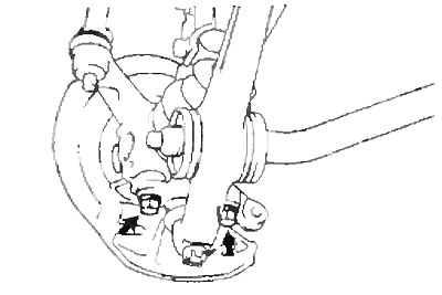
8 Using a plastic hammer, unhook the drive shaft from the hub.
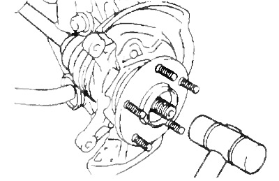
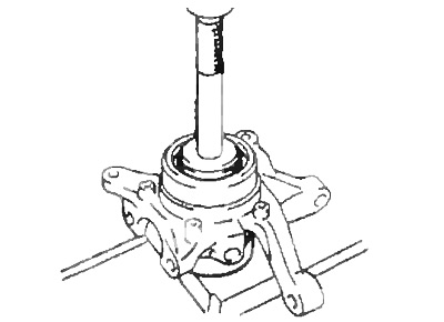
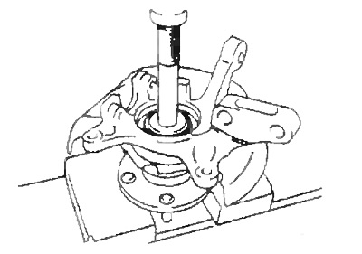
9. Remove a rotary fist in gathering with a nave.
A) Remove the bolts from the underside of the rack.
b) Remove the steering knuckle with the hub.
Installation note:
- Coat the nut threads with engine oil.
- be careful not to damage the boot, the inner seal and the speed sensor rotor teeth on the drive shaft.
Disassembly
1. Using a screwdriver, remove the boot.
2. Using a puller, remove the circlip.
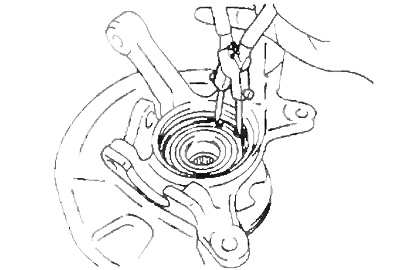
3. Remove the hub.
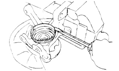
A) Using a puller, remove the hub from the steering knuckle.
b) Press the bearing inner race off the hub.
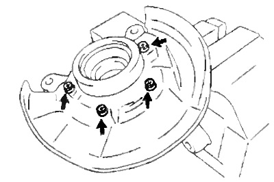
4. Turn away four bolts and remove a splash guard.
5. Remove the bearing from a rotary fist.
A) Install the inner race on the bearing.
b) Press out the bearing.
Assembly
1. Install the bearing.
A) Press the new bearing into the steering knuckle.
b) Install a new retaining ring
2. Install the splash guard and tighten the four bolts.
- Tightening torque - 8.5 Nm
3. Press in the hub.
4. Using the special tool, install a new circlip.
5. Using the special tool and a hammer, install a new boot.
Note: Align the holes for the ABS sensor in the boot and steering knuckle.
Hub bolt replacement
1. Jack up the car, remove the front wheel.
2. Remove the caliper assembly and brake disc.
Note: Mark alignment marks on the brake disc and hub.
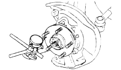
3. Using the special tool, remove the hub bolt.
4. Install the hub bolt.
A) Install the washer and nut on the hub bolt as shown.
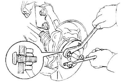
b) Install the bolt while tightening the nut.
5. Install the brake disc.
Note: Align the alignment marks on the brake disc and hub made during disassembly.
6. Install the caliper and tighten the bolts.
- Tightening torque - 109 Nm
7. Install the front wheel and lower the vehicle.
- Tightening torque - 105 Nm