



Contents: Examination ↓ Replacement ↓
Elements of the radiator fan hydraulic drive system
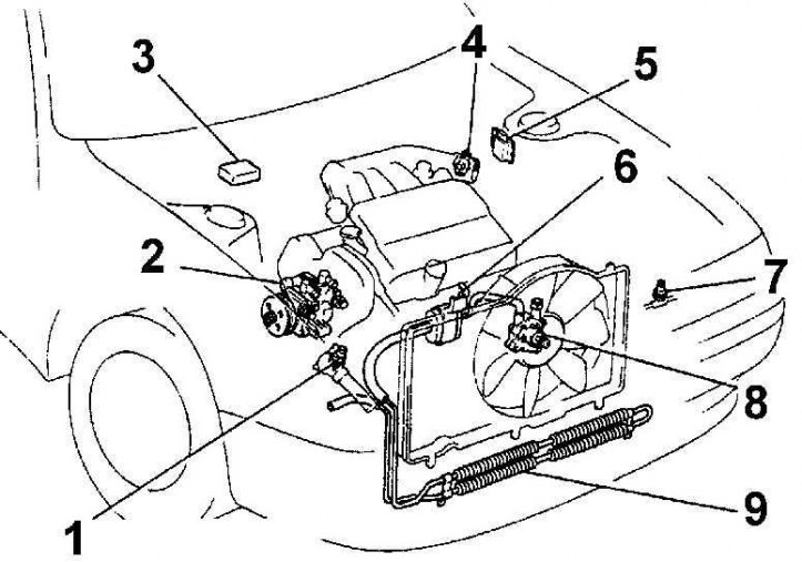
1 – coolant temperature sensor; 2 - hydraulic pump; 3 - Radiator Fan Control Unit (ECU); 4 - throttle position sensor; 5 - ignition unit; 6 - oil filter; 7 - pressure sensor; 8 - hydraulic motor; 9 - oil radiator
Models with V6 engines from 1992 to 1994 have a hydraulically driven radiator fan. The power steering pump on these models has two additional hoses that supply fluid to the power steering mechanism and the radiator fan. The fan is controlled by the radiator fan electronic control unit (ECU) and a solenoid valve that regulates the amount of fluid supplied to the radiator fan.
Examination
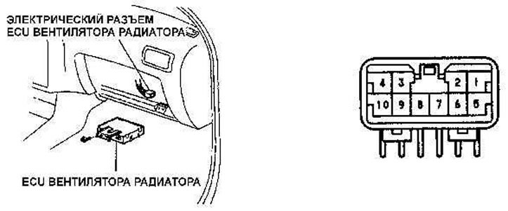
Location of the radiator fan control unit, contacts on the electrical connector
[The article was copied from the portal: TOYOTAMAN]
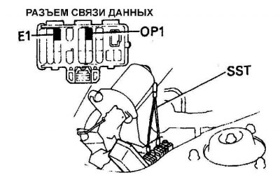
1. Connect the additional wire between the E1 and OP1 contacts of the electrical connector. The radiator fan should rotate at a speed of approximately 1100 rpm.
2. The radiator fan control unit is located under the glove box. To check the radiator fan control circuits, remove the lower instrument panel cover and glove box and disconnect the electrical connector from the ECU.
3. Check the electrical circuits according to the Electrical Circuit Checking table.
4. To check the coolant temperature sensor, disconnect the electrical connector from the sensor and remove the sensor. Connect an ohmmeter to the sensor contacts, place the sensor in a container with hot water and measure its resistance. The sensor resistance at a water temperature of 80°C should be within 1480–1580 Ohms.
5. To check the solenoid valve, disconnect the electrical connector from it and check the resistance of the solenoid valve winding, which should be 7.6-8 ohms at 25°C.
Checking electrical circuits
| Control | Tester connections | Condition | Meaning |
| Voltage | 1 – Mass | Ignition is on | Battery voltage |
| Resistance. | 2–3 | Solenoid valve cold (25 C) | 7.6 – 8.0 Ohm |
| Compound | 4 – Mass | The throttle valve is open | Closed |
| Compound | 5 – Mass | The throttle valve is closed | Not closed |
| Compound | 8 – Mass | A/C pressure connector disconnected | Not closed |
| A/C pressure connector connected | Closed | ||
| Resistance. | 9–10 | Coolant temperature 80 C | 1.48 – 1.58 kOhm |
Replacement
1. To replace the fan or fan motor, drain the coolant and remove the upper radiator hose.
2. Unscrew the connecting bolts and disconnect the pressure hose from the fan motor.
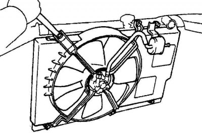
3. Disconnect the return hose. Unscrew the six bolts securing the fan shroud to the radiator and remove the fan together with the shroud.
4. Secure the shaft of the hydraulic fan motor from turning and, rotating the fan blades clockwise, unscrew them from the shaft (left hand thread).
5. Remove the three bolts securing the motor to the fan shroud and remove the motor.
6. Installation is carried out in the reverse order of removal.