
Examination
Location of the temperature sensor for turning on the radiator fan in the lower radiator tank on models with four-cylinder engines
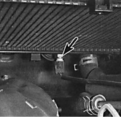
The fan is controlled by a temperature sensor installed in the radiator.
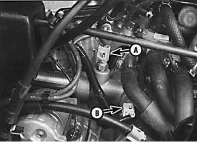
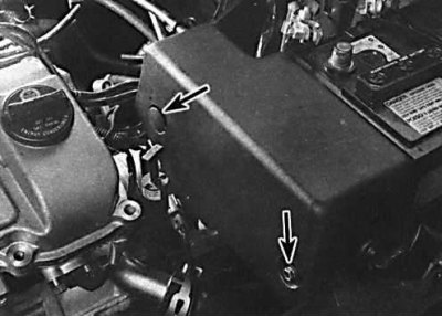
On the 1MZ-FE V6 engine, thermal sensors No. 1 (A) and no. 2 (IN) located on the thermostat housing.
Checking the resistance of thermal sensors on the 1MZ-FE V6 engine
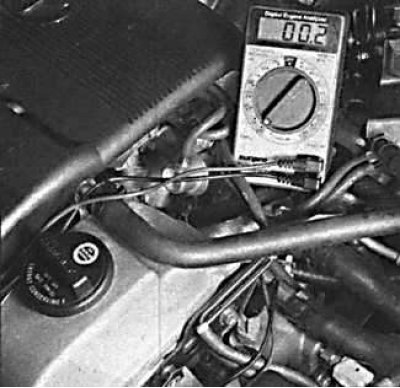
On a cold engine, the resistance of sensor #1 should be 0.
Checking the health of the radiator fan motor by applying voltage to it with additional wires from the battery
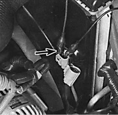
The fan should turn on when the operating temperature of the engine is exceeded, that is, a few minutes before the arrow of the engine temperature gauge enters the red sector. If the fan does not turn on, remove the wires from the temperature sensor, connect them together and turn on the ignition. If the fan then starts working, the temperature sensor is probably out of order, which must be replaced. If the fan still does not work, check if the voltage is applied to the temperature sensor. If there is no voltage at the temperature sensor, the wires may be damaged, or the fuse may have blown. If voltage is applied, check the reliability of the connection to the ground of the second wire of the sensor. If the temperature sensor and wiring are in good condition, the fan motor may be damaged. The electric motor can be tested by applying voltage to it with additional wires from the battery.
Relay test
Location of the main relay box and radiator fan relay on models with 5S-FE engines
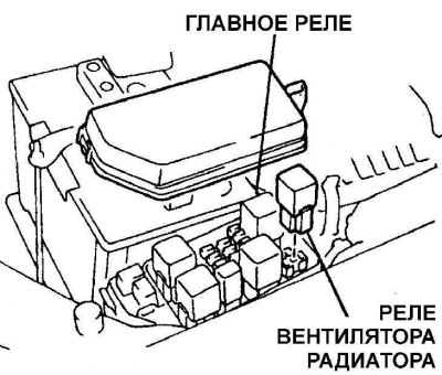
The main relay box is located in the engine compartment on the driver's side. Air conditioning models have relay #2.
Location of the relay in the relay box on models with 1MZ-FE engines
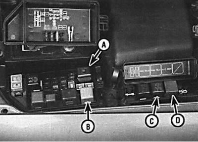
a - the main relay of the engine;
b - radiator fan relay No. 1;
c - radiator fan relay No. 2;
d - radiator fan relay No. 3
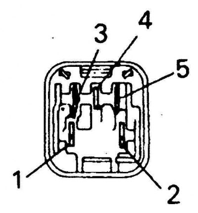
The location of the contacts of the main relay of the engine
Resistance Test and Radiator Fan Relay #1 Location
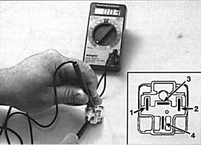
1. Remove the #1 radiator fan relay and use an ohmmeter to check the resistance between the relay contacts (see fig. Resistance Test and Radiator Fan Relay #1 Location). The resistance between relay contacts 1 and 2 and contacts 3 and 4 must be minimal. When applying voltage from the battery to pins 1 and 2, the resistance between pins 3 and 4 should be equal to infinity.
2. If the radiator fan relay is good, remove the main engine relay and check it (see fig. Resistance check and arrangement of contacts of the relay of the fan of a radiator No. 1 and fig. The location of the contacts of the main relay of the engine). The resistance between relay contacts 3 and 5 and contacts 2 and 4 must be minimal. The resistance between pins 1 and 2 should be infinity. When battery voltage is applied to pins 3 and 5, the resistance between relay pins 1 and 2 should be minimal, and the resistance between pins 2 and 4 should be equal to infinity.
Replacement
1. Remove the ground wire from the battery.
Attention! If your radio has an anti-theft code, check that you have the pairing codes before disconnecting the battery.
Attention! On models since 1993, the airbag system is disabled if the battery is disconnected for an extended period. If the airbag warning light comes on and stays on after reconnecting the battery, take it to a specialist workshop to restore the system to normal.
2. Disconnect the electrical connector from the radiator fan motor.
 | 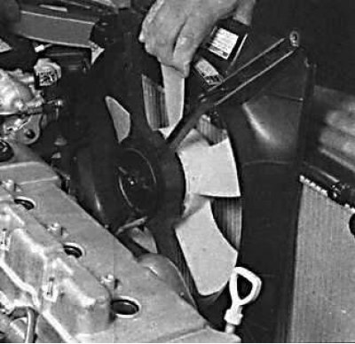 |
3. On models with cruise control, remove the cruise control actuator shroud for easier removal of the radiator fan.
4. Remove the fan shroud-to-radiator bolts and remove the fan assembly from the vehicle.
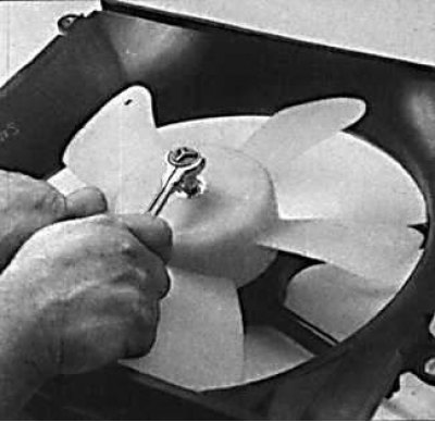 |  |
5. While holding the fan blades from turning, unscrew the fastening nut and remove the fan from the motor.
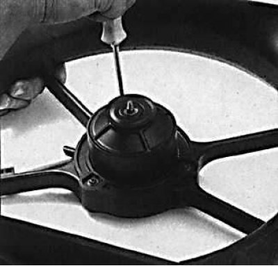
6. Remove the bolts securing the radiator fan motor to the fan shroud.
7. Installation is made in sequence, return to removal.