
Removing
Note: Install in the reverse order of removal.
1. Disconnect the speed sensor connector.
A) Remove the cover.
b) Disconnect the connector.
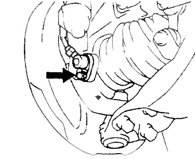
2. Remove the speed sensor.
A) Loosen the sensor wiring harness bolts.
- Tightening torque during installation - 5.5 Nm
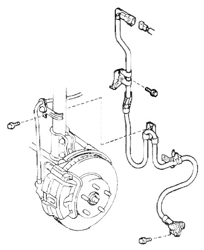
b) Remove the speed sensor from the steering knuckle.
- Tightening torque during installation - 8 Nm
Examination
1. Check the front wheel speed sensors.
A) Remove the cover.
b) Disconnect the speed sensor connector.
V) Measure the resistance between the terminals of each sensor connector.
- Rated resistance - 0.6 -1.8 kOhm
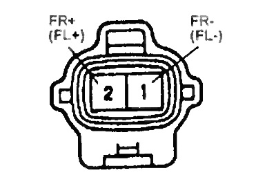
If the value is out of specification, replace the sensor.
G) Check for continuity between each of the terminals and the sensor body. If there is continuity, replace the sensor.
d) Connect the speed sensor connectors.
e) Install fender liner
2. Check that the wheel speed sensor is correctly installed and that the tightening torque of the sensor fastening bolt is within acceptable range.
- Tightening torque - 7.8 Nm
3. Visually check the rotor teeth of the wheel speed sensor.
A) Remove the drive shaft.
b) Check sensor rotor teeth for scratches, cracks, deformation, or missing teeth
V) Install the drive shaft.
Caution: To prevent damage to the encoder rotor teeth, do not strike the drive shaft.
Checking the front wheel speed sensor
1. Connect the oscilloscope to the speed sensor connector.
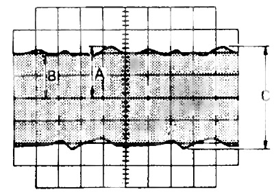
2. While driving at 20 km/h, check the waveform.
3. Check that "WITH" = 0.5 V or more. If not, replace the sensor
4. Make sure that "IN" is 30% or more of "A". If not, replace the drive shaft.