Parking brake disassembly
1. Remove the rear wheel.
2. Remove the rear caliper assembly.
A) Remove the two mounting bolts and remove the rear caliper assembly.
b) Hang the caliper so as not to stretch the hose.
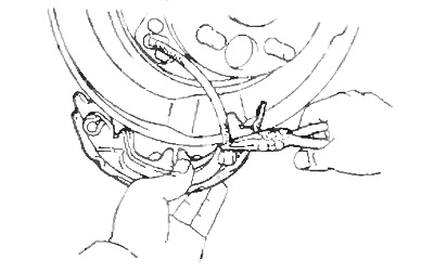
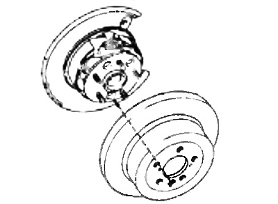
3. Remove the brake disc.
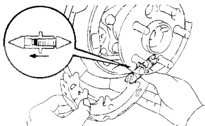
Note: If the brake disc cannot be removed, rotate the adjuster to reduce its length.
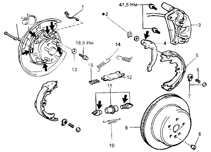
Parking brake for rear disc brakes.
1 - holder,
2 - lock washer,
3 - caliper assembly,
4 - parking brake lever,
5 - brake shoe,
6 - holder spring,
7 - spring seats,
8 - plug,
9 - brake disc,
10 - return spring,
11 - regulator,
12 - spacer plate,
13 - guide,
14 - coupling spring pads,
15 - spring.
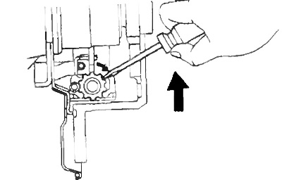
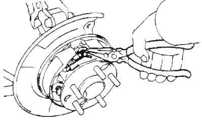
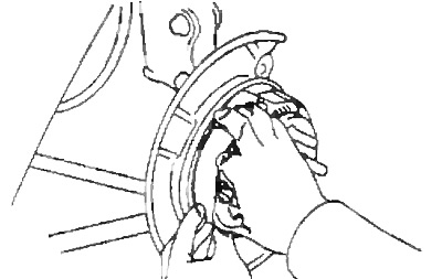
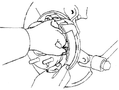
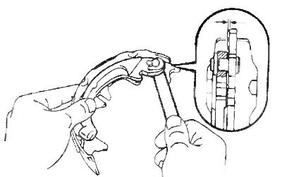
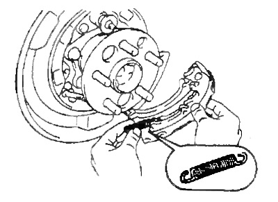
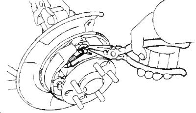
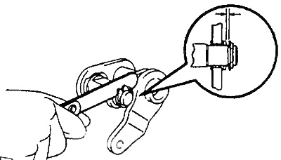
4. Using the special tool, remove the shoe return springs.
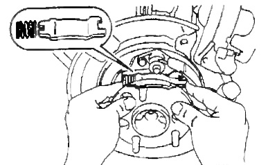
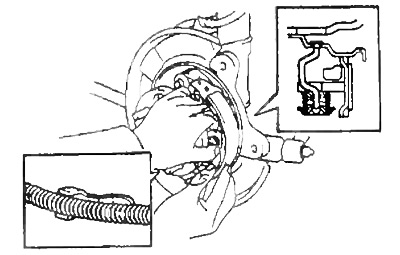
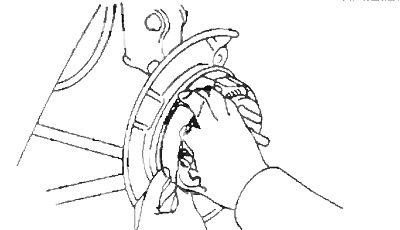
5. Remove the retainer spring, spring seats and retainer.
6. Remove the front brake shoe and adjuster.
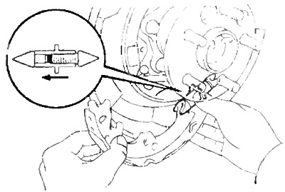
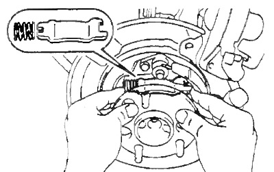
A) Remove the spacer plate with spring.
b) Remove the regulator.
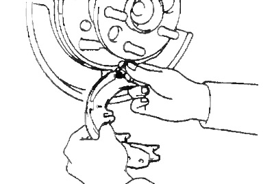
V) Disconnect the return spring and remove the front shoe.
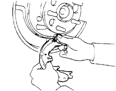
7. Remove the rear brake shoe, and) Remove the retainer spring, spring seats and retainer.
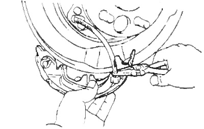
b) Remove the return spring from the rear shoe.
V) Disconnect the parking brake cable from the parking brake lever.
8. Remove the lock washer and parking brake lever from the brake shoe.
Checking the parking brake
1. Check the removed parts for wear, rust or damage.
2. Using a ruler, measure the thickness of the brake pads.
- Standard thickness - 2.0 mm
- Minimum thickness - 1.0 mm
Replace the brake pads if the brake lining thickness is less than the minimum allowable or uneven lining wear is detected.
3. Using a vernier caliper, measure the inside diameter of the brake disc.
- Standard - 170 mm
- Maximum allowable - 171 mm
Replace the brake disc if the inside diameter is larger than the maximum.
4. Check the fit of the brake shoe lining to the drum (disk).
If the contact between the working surfaces is poor, then replace the brake pads.
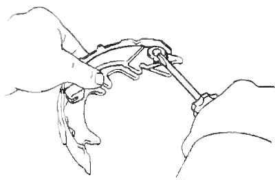
5. Using a feeler gauge, measure the clearance between the brake shoe and the parking brake lever.
- The maximum allowable gap is 0.35 mm
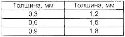
If the gap is not within specifications, then fit a shim of the desired thickness from the values given in the table.
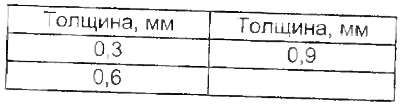 |  |
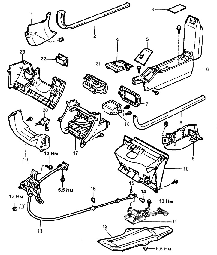
Removal and installation of a cable of a lay brake.
1, 9 - side trim,
2, 8 - trim front door sill,
3 - mat,
4 - finishing holes for the manual transmission lever,
5 - lining of the rear part of the center console,
6 - rear of the center console,
7 - lower trim of the center console,
10 - glove box,
11 - bracket,
12 - overlay (3S-FE, 4WS),
13 - parking brake cable,
14 - fork axle,
15 - cotter pin,
16 - cable holder,
17 - front part of the center console,
18 - heater control panel assembly,
19 - air duct,
20 - hood lock lever,
21 - central finishing panel,
22 - additional glove box,
23 - lower trim panel on the driver's side.
6. Replace, if necessary, an adjusting washer.
A) Remove the parking brake lever, and install the shim of the correct thickness.
b) Install the parking brake lever with a new lock washer.
V) Re-measure the clearance.
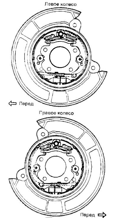
Setting the parking brake
Note: install the parts as shown in the picture.
1. Apply high-temperature grease to the brake shield, in the places indicated by the arrows in the assembly drawing.
2. Apply high temperature grease to the regulator as shown.
3. Install the rear shoe.
A) Connect the parking brake cable to the lever.
b) Install the return spring.
V) Install retainer, spring seats and retainer spring.
4. Install spacer plate.
5. Install the front shoe.
A) Connect the return spring to the front shoe.
b) Install the adjuster between the front and rear shoes as shown.
V) Install retainer, spring seats and retainer spring.
6. Using the special tool, install the shoe return springs.
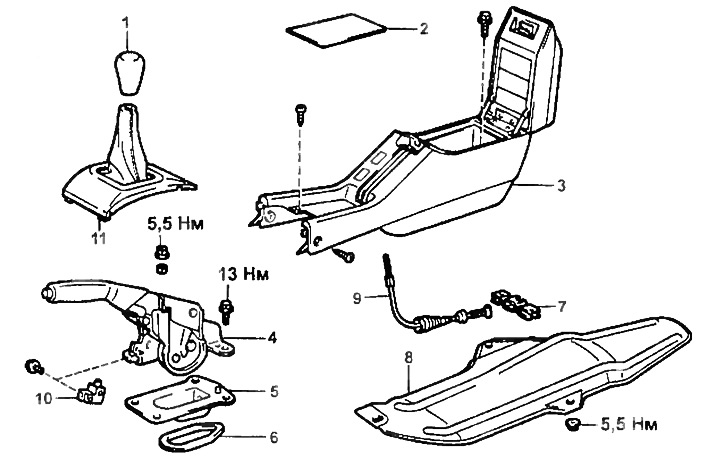
Parking brake lever.
1 - manual transmission handle,
2 - mat,
3 - rear of the center console,
4 - parking brake lever,
5 - bracket,
6 - seal,
7 - holder,
8 - overlay (3S-FE, 4WS),
9 - parking brake cable,
10 - parking brake activation sensor,
11 - manual transmission lever trim.
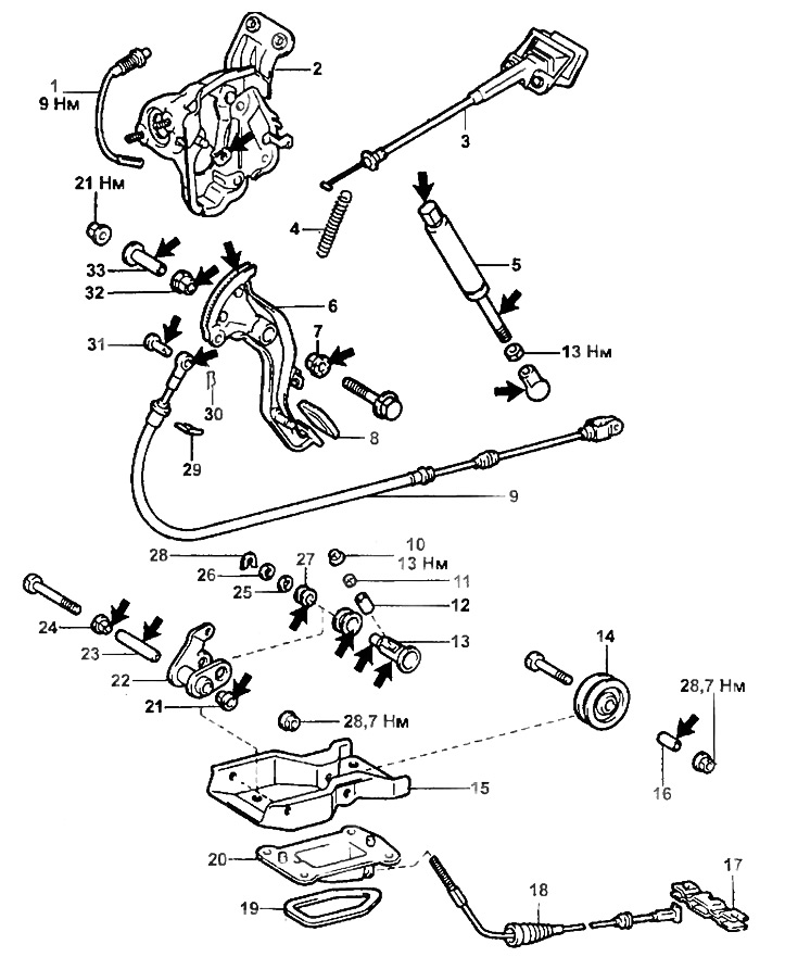
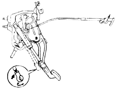
Parking brake pedal.
1 - parking brake activation sensor,
2 - housing of the parking brake mechanism,
3 - handle for disengaging the parking brake,
4 - spring,
5 - shock absorber,
6 - parking brake pedal,
7 - bushing,
8 - pedal pad,
9 - parking brake cable,
10 - locknut,
11 - bushing,
12 - bushing,
13 - axis,
14 - roller,
15 - support bracket,
16 - bushing,
17 - latch,
18 - parking brake cable,
19 - seal,
20 - bracket,
21, 24 - plastic bushings,
22 - bracket,
23 - bushing,
25, 26 - washer,
27 - bushing,
28 - retaining ring,
29 - latch,
30 - cotter pin,
31 - pin,
32 - bushing,
33 - pedal axis.
7. Check the correct installation of parts according to the figure.
8. Install the brake disc.
A) Before assembling, sand the disc and pad surfaces with sandpaper.
b) Align the hole on the rear axle hub with the hole on the rim.
Caution: Do not allow oil or grease to come into contact with friction surfaces.
9. Adjust the clearance of the parking brake shoes.
A) Temporarily install wheel nuts.
b) Remove the plug.
V) Turn the adjuster to move the pads apart until they block the disc.
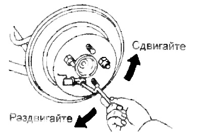
G) Loosen the adjuster eight teeth.
d) Install a trap.
10 Install the rear caliper assembly and tighten the two mounting bolts.
- Tightening torque - 47 Nm
11. Install the rear wheel.
- Tightening torque - 105 Nm
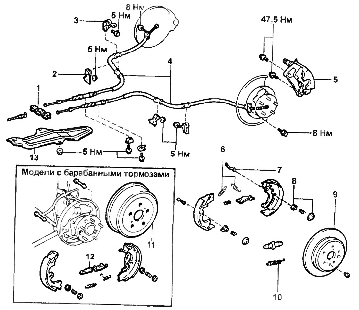
Parking brake cables (2WD).
1 - latch,
2 - cable bracket No. 1,
3 - cable bracket No. 2,
4 - parking brake cable,
5 - caliper assembly,
6 - coupling spring,
7 - shoe holder,
8 - saddle,
9 - brake disc,
10 - return spring,
11 - brake drum,
12 - regulator,
13 - overlay (3S-FE, 4WS).
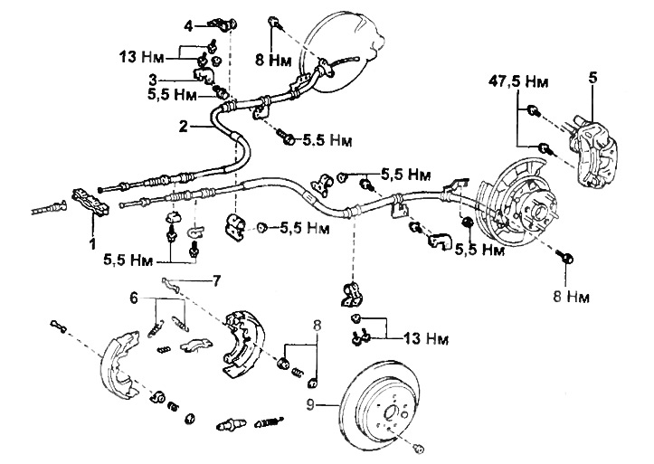
Parking brake cables (4WD).
1 - latch,
2 - parking brake cable,
3 - cable bracket No. 1,
4 - cable bracket No. 2,
5 - caliper assembly,
6 - coupling spring,
7 - pad holder,
8 - saddle,
9 - brake disc.
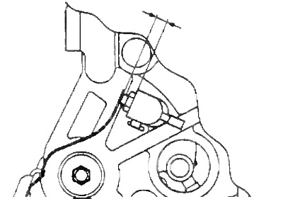
Checks and adjustments
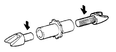
1. Installing the stem.
A) Loosen the shock absorber locknut.
b) Connect the shock absorber to the brake pedal and fully extend the rod.
V) Press the pedal until it touches the stops.
G) Rotate the stem tip until the hole on the stem matches the stem on the pedal. Then turn the tip to the left one turn.
d) Connect the damper tip to the pedal stem and tighten the locknut.
- Tightening torque - 13 Nm
Note: when connecting a shock absorber, its stem must be recessed by 0.5-2.0 mm.
e) By rotating the parking brake sensor so that the gap shown in the figure is within the specified range.
- Nominal clearance - 6.5-9.5 mm
2. Using a feeler gauge, measure the clearance between the pedal shaft and the bracket.
- The maximum allowable gap is 0.09 - 0.5 mm
If the gap does not match the specified, then select the shim of the desired thickness (see table).