
2. Establish bolts of fastening of a head of the block of cylinders.
Note:
- The cylinder head bolts are tightened in two stages.
- If any cylinder head bolt is broken or deformed, replace it.
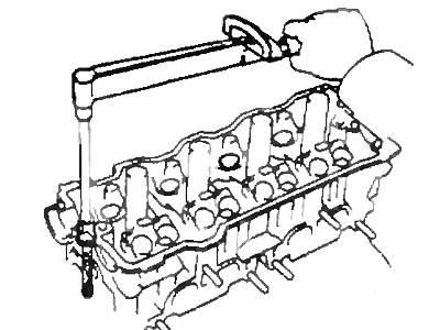
A) Apply a light coat of engine oil to the threads and under the heads of the mounting bolts.
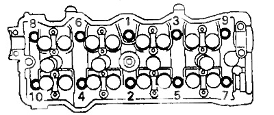
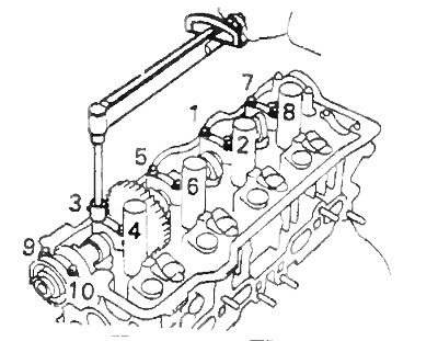
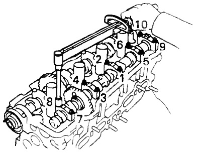
b) Install and evenly tighten the 10 cylinder head bolts and plate washers in several passes in the sequence shown.
- Tightening torque - 49 Nm
If any bolt is not tightened to the correct torque, replace the bolt.
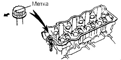
V) Apply paint marks to the front of the cylinder head bolts.
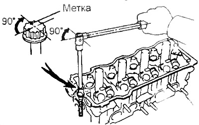
G) Tighten the cylinder head bolts 90°in the above sequence.
d) Check that the inked mark is 90 from its original position.
2. Install spark plug tubes (if filmed).
A) Clean the spark plug tube holes in the cylinder head. Remove oil with kerosene or gasoline.
b) Apply sealant to the threads of the spark plug tubes and install the tubes to the cylinder head.
V) Using the spark plug tube nut and 30mm socket wrench, tighten the spark plug tubes.
- Tightening torque - 39 Nm
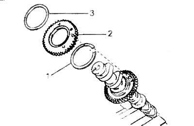
3. Assemble the exhaust camshaft (if dismantled).
A) Install the camshaft in a vise.
Note: be careful not to damage the camshaft.
b) Install the following parts:
- (1) Camshaft gear snap ring.
- (2) Auxiliary camshaft drive gear.
- (3) Spring washer.
Note: Align the drive pins on the gears with the ends of the spring.
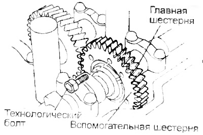
V) Using a tool, install the circlips.
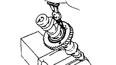
G) Insert process bolt "A" into the technological hole of the auxiliary gear of the camshaft drive.
d) Using a screwdriver, align the hole of the camshaft drive main gear and the sub gear by turning the camshaft drive sub gear clockwise; then install the technological bolt (IN).
Note: Do not damage the camshaft.
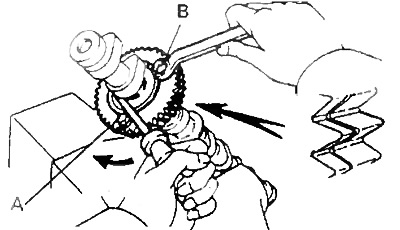
e) Align the teeth of the main and auxiliary gears, and tighten the service bolt B.
4. Install camshafts. Note: when installing camshafts, it must be taken into account that the value of the axial clearance is very small; therefore, the shafts must be laid in the bed of bearings strictly horizontally, without distortions, in order to avoid jamming and / or damage to the shafts.
A. Install the intake camshaft.
A) Apply a layer of engine oil to the end thrust surfaces of the camshaft.
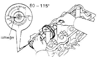
b) Set the intake camshaft to 80-115°until the No. 1 cylinder is at TDC.
Note: At these angles, the lobes on the No. 1 and No. 3 cylinders of the intake camshaft press on the tappets.
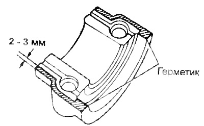
V) Apply sealant to bearing cap #1 as shown.
G) Install the bearing caps in accordance with the markings on their housings.
d) Apply a light coat of engine oil to the threads and under the heads of the bearing cap bolts.
e) Install and evenly tighten the 10 bearing cap bolts in several passes in the sequence shown.
- Tightening torque - 19 Nm
and) Apply grease to the new oil seal.
h) Using a mandrel of suitable diameter and a hammer, install the oil seal.
B. Install the exhaust camshaft.
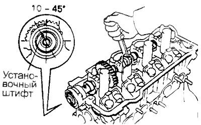
A) Set the inlet camshaft locating pin to 10 - 45°BTDC.
Note: At these angles, the lobes on the No. 2 and No. 4 camshaft cylinders of the intake camshaft press the pushrods.
b) Apply a layer of engine oil to the end thrust surfaces of the camshaft.
V) Engage the exhaust and intake camshaft drive gears by aligning the alignment marks on the gears with each other.
G) Keeping the gears engaged, roll the exhaust camshaft into its journals on the cylinder head.
Note: If there are also match marks on the gears, as shown in the picture, then do not use these marks for installation.
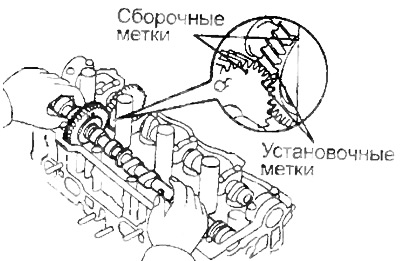
d) Rotate the intake camshaft clockwise until the exhaust camshaft is seated in the bearing journals without rolling.
Note: It is very important to follow the tightening sequence of the bearing cap bolts in the following steps.
e) Install bearing caps.
and) Apply a light coat of engine oil to the threads and under the heads of the bearing cap bolts.
h) Install and evenly tighten the 10 bearing cap bolts in several passes in the sequence shown.
- Tightening torque - 19 Nm
And) unscrew the technological bolt "IN".
To) Turn the camshafts and check the alignment of the marks on the gears.
5. Turn the camshaft and place the cams with the working projections up, check and adjust, if necessary, the clearance in the valve drive.
Valve clearance (cold engine):
- intake - 0.19-0.29 mm
- graduation 0.28-0.38 mm
6. Install segment plugs (if filmed).
A) Remove old sealing material.
b) Apply sealant to the segment plugs as shown.
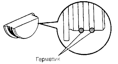
V) Install two segment plugs in the cylinder head.
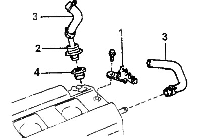
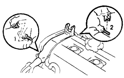
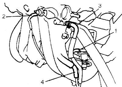
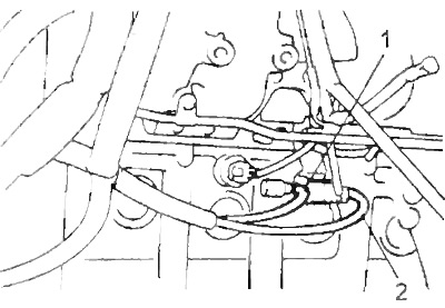
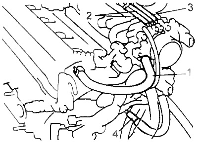
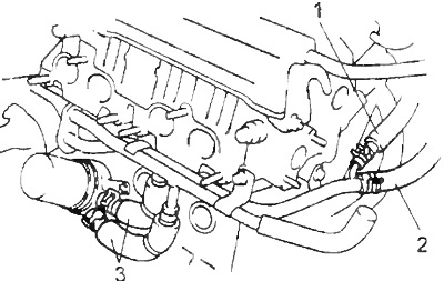
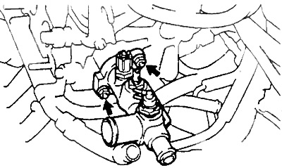
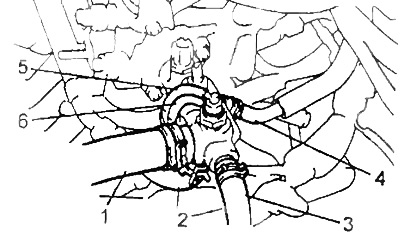
7. Install the high voltage wire clamps, crankcase ventilation valve and hose from the cylinder head cover.
A) Install high voltage wire clamps (1), by tightening the bolt.
b) Install the crankcase ventilation valve (2) having previously lubricated it with a sealant before installation, the hose (3) and seal (4).
V) Install the crankcase ventilation hose (3).
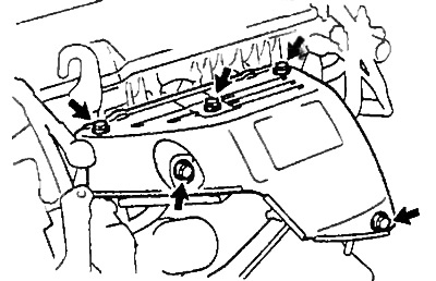
8. Install the cylinder head cover.
A) Remove the remnants of the old gasket.
b) Apply sealant to the cylinder head as shown.
Note: If using an old gasket, lubricate the entire surface.
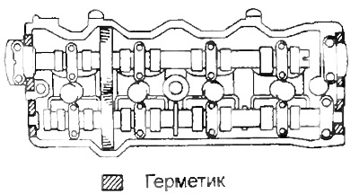
V) Install the gasket on the cylinder head cover.
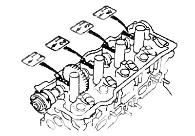
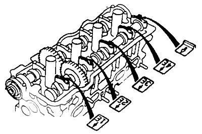
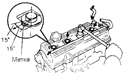
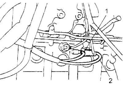
G) Install the cylinder head cover and spark plug tube seals with nuts. Tighten the nuts evenly in several passes.
- Tightening torque - 23 Nm
Note: Install the spark plug tube seals so that their marks are located as shown in the illustration.
9. Install the oil pressure sensor, having previously applied a special fixing adhesive (or sealant) on 2 or 3 threads of the sensor.
10. Install the alternator bracket and right engine lifting hook by tightening the three bolts.
- Tightening torque - 42 Nm
11. Install the rear timing belt cover by tightening the four bolts.
- Tightening torque - 8 Nm
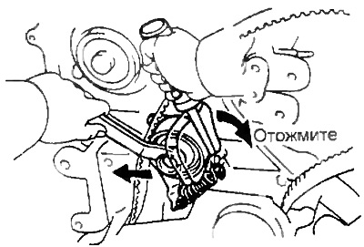
12. Temporarily install the tension roller and spring.
A) Align the bracket guide pin hole with the pin.
b) Install the tension roller and bolt; do not tighten the bolt.
V) Install the tensioner spring.
G) Press the roller to the left as far as possible and tighten the bolt.
d) Check that the tension roller moves freely.
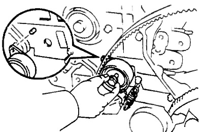
13. Install the camshaft sprocket.
A) Align the camshaft locating pin with the locating pin groove, and install the camshaft sprocket onto the shaft.
b) Tighten the pulley bolt.
- Tightening torque - 54 Nm
14. Install the timing belt on the camshaft sprocket.
A) Rotate the crankshaft until its alignment marks are aligned.
b) Install and check the alignment of the crankshaft and camshaft pulley marks.
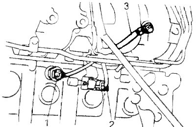
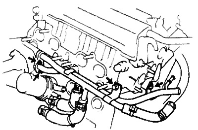
15. Install the injectors into the fuel manifold.
A) Install new sealing bushings on each nozzle.
b) Apply a thin coat of fuel to the O-rings.
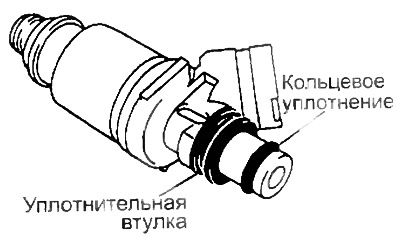
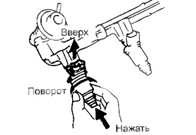
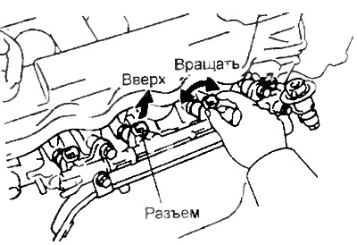
V) Rotate the injectors, press them against the fuel manifold and install the injectors.
G) Install the injector connector up.
d) Install four new insulators and two spacers.
Note: It is better to glue the bushings.
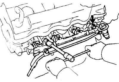
e) Install the fuel manifold with injectors to the cylinder head.
and) Temporarily tighten the two bolts securing the fuel manifold to the cylinder head.
h) Check the smooth rotation of the nozzles.
Note: If the nozzles do not rotate evenly, the likely cause is incorrect O-ring installation. Replace O-ring.
And) Install the injector connectors up.
To) Tighten the two bolts securing the fuel manifold to the cylinder head.
- Tightening torque - 13 Nm
l) Connect the injector connectors.
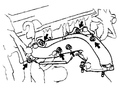
16. Install the intake manifold.
A) Install the new gasket and intake manifold by tightening the six bolts and two nuts in several passes
- Tightening torque - 19 Nm
b) Install the two engine wire clamps to the wire brackets on the intake manifold.
V) Install the two engine harness guard clamps to the timing belt upper cover mounting bolts in the sequence shown.
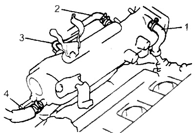
G) Connect the following hoses:
- (1) Crankcase ventilation hose to intake manifold.
- (2) A/C idle boost valve vacuum hose to intake manifold.
- (3) Vacuum hose from intake manifold absolute pressure sensor to gas filter.
- (4) Brake booster vacuum hose to intake manifold.
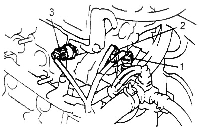
17. (Models with exhaust gas recirculation) Install the EGR valve by tightening the bolt.
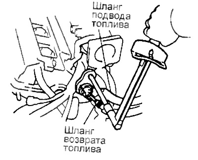
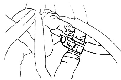
18. Connect the fuel return hose to the tube.
19. Connect the fuel supply hose to the fuel manifold.
A) Temporarily connect the fuel supply hose with two new gaskets and a fuel pressure pulsation damper.
b) Install the fuel pressure pulsation damper.
- Tightening torque - 34 Nm
V) Install the engine wiring harness clamp and electrical wiring clamp.
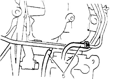
20. Install the vacuum tube.
A) Install the vacuum tube by tightening the two bolts.
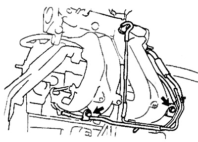
b) Connect the following hoses:
- (1) vacuum hose (from the gas filter) to the fuel pressure regulator.
- (2) vacuum hose (from the fuel pressure regulator) to the gas filter.
- (3) Power steering pump air control valve vacuum hose to intake manifold.
- (4) Vacuum hose for the idle speed increase valve when the air conditioner is turned on.
(5) Two vacuum hoses for the power steering pump air bypass valve.
21. Connect:
- (1) knock sensor connector
- (2) (Models with exhaust gas recirculation) connector for the electropneumatic valve of the exhaust gas recirculation system,
- (3) the wire "masses".
22. Install intake manifold bracket #1 by tightening the two bolts.
- Tightening torque - 42 Nm
23. (Models with exhaust gas recirculation) Install the EGR valve and vacuum modulator.
A) Install a new gasket and EGR valve by tightening the union nut and the two mounting nuts.
Torque:
- fastening nuts - 13 Nm
- union nut - 59 Nm
b) Connect the following hoses:
- (1) vacuum hose (from the exhaust gas recirculation valve) to the channel "E" electropneumatic valve of the exhaust gas recirculation system.
- (2) vacuum hose (from the channel "Q" EGR pressure modulator) to the channel "G" electropneumatic valve of the exhaust gas recirculation system.
24. Install intake manifold bracket #2 and left engine lifting hook by tightening bolt and nut.
- Tightening torque - 42 Nm
25. Install the throttle body.
A) Install a new gasket on the intake manifold, tab down.
b) Install the throttle body by tightening four bolts or two bolts and two nuts.
- Tightening torque - 19 Nm
Note: different bolt lengths are used: top and bottom.
Bolt length:
- top - 40 mm
- bottom - 55 mm
V) Connect the following hoses:
- (1) Crankcase ventilation hose to throttle body.
- (2) (Models with exhaust gas recirculation system) Two vacuum hoses (from the pressure modulator of the exhaust gas recirculation system) to the throttle body.
- (3) (Models with evaporative emission system) vacuum hose (from the thermally controlled pneumatic valve of the fuel vapor recovery system) to the throttle body.
- (4) vacuum hose (from idle control valve) to the tube.
d) Connect the following connectors:
- (1) Throttle position sensor connector,
- (2) Idle air control valve connector.
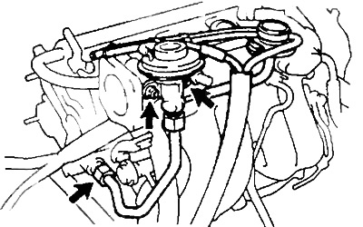
26. Install the coolant bypass pipe.
A) Install a new gasket to the water pump cover.
b) Install a new O-ring on the coolant overflow pipe.
V) Apply soapy water to the O-ring.
G) Connect the coolant overflow pipe to the coolant pump cover.
d) Install the coolant overflow pipe by tightening the two nuts and two bolts.
Torque:
- nuts - 9 Nm
- bolts - 19 Nm
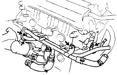
e) Connect the following hoses:
- (1) Idle air control valve coolant bypass hose to coolant bypass pipe.
- (2) Heater hose to coolant overflow pipe.
- (3) (Models with oil cooler) Two oil cooler bypass hoses.
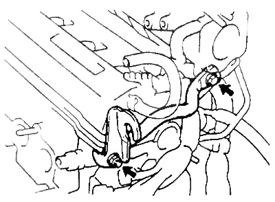
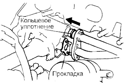
27. Install the coolant outlet.
A) Install a new gasket and coolant outlet fitting by tightening the two nuts.
- Tightening torque - 15 Nm
b) Connect the following hoses:
- (1) upper radiator hose,
- (2) coolant bypass hose,
- (3) heater hose,
- (4) Idle Air Control Valve Coolant Bypass Hose,
- (5) (Models with evaporative emission system) vacuum hose of thermally controlled pneumatic valve (from the channel "R" throttle body),
- (6) (Models with evaporative emission system) vacuum hose of thermally controlled pneumatic valve (from fuel vapor accumulator).
V) Connect the following connectors:
- (1) Coolant temperature gauge sensor connector;
- (2) Coolant temperature sensor connector;
- (3) Oil pressure sensor connector.
29. Install the exhaust manifold.
A) Install the lower heat shield to the exhaust manifold by tightening the three bolts.
b) Install the new gasket and exhaust manifold by tightening the six nuts evenly and in several passes.
- Tightening torque - 49 Nm
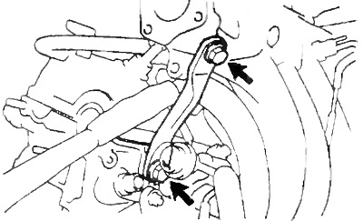
V) Install the manifold bracket by tightening the bolt and nut and install the downpipe.
- Tightening torque - 42 Nm
G) Install the top heat shield by tightening the five bolts.
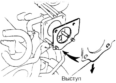
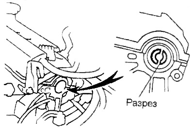
30. Install the distributor.
A) Rotate the crankshaft clockwise, and install the section of the intake camshaft as shown in the figure.
 |  |
b) Check the condition of the O-rings and replace if necessary.
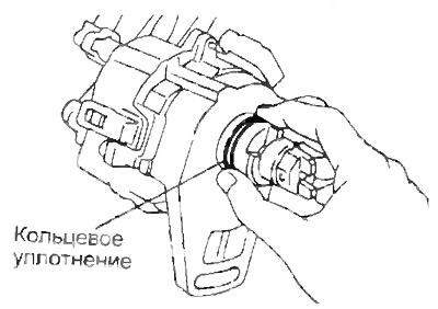
V) Apply a thin coat of engine oil to the O-ring.
G) Align the notch of the coupling with the protrusion on the body
d) Insert the distributor, align the center of the flange with the bolt hole on the cylinder head.
Note: The cut is off-center and therefore the distributor can only be inserted one way.
e) Lightly tighten the two bolts.
and) Connect the high voltage wires to the spark plugs.
h) Connect the two distributor connectors.
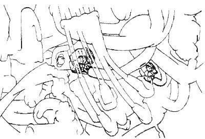
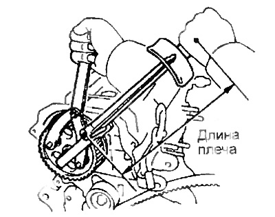
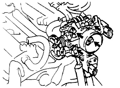
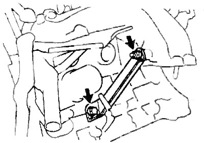
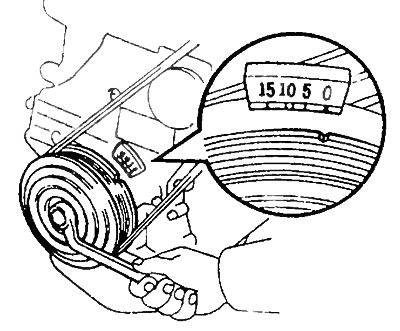
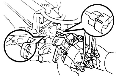
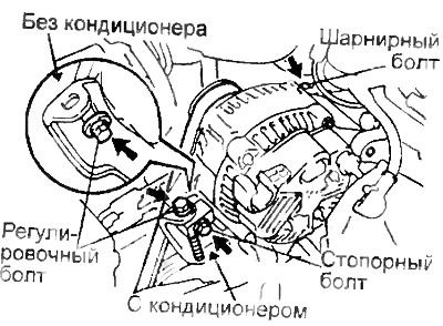
31. Install the generator.
A) Install alternator pivot, locking bolt (models with air conditioning) or adjusting bolt (models without air conditioning). Do not overtighten the bolts.
b) Install the alternator drive belt.
V) Adjust belt tension.
G) Tighten hinge bolt, lock bolt (models with air conditioning) and adjusting bolt (models without air conditioning)
Torque:
- hinge bolt - 54 Nm
- locking bolt or adjusting bolt - 19 Nm
d) Connect the generator connector.
e) Connect the generator wire, tighten the nut and install the rubber cap.
and) Install the electrical wiring clamp to the clamp on the generator.
32. Install the throttle cable bracket by tightening the two bolts
33. Fill the radiator with coolant.
34. Connect the control cables.
35. Connect the negative battery terminal.