



Warning! If your radio has an anti-theft code, check that you have the connection codes before disconnecting the battery.
Caution! On models from 1993 onwards, the airbag system is disabled if the battery is disconnected for an extended period of time. If the airbag warning light comes on and remains on after the battery is reconnected, contact a specialist workshop to restore the system to working order.
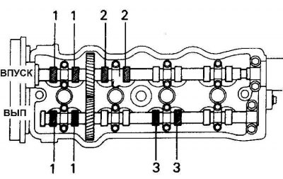
Fig. 1
On a four-cylinder engine, when the piston of the first cylinder is set to the top dead center in the compression stroke, it is necessary to measure the clearance of the exhaust valves in cylinders No.1 and No.3 and the intake valves in cylinders No.1 and No.2.
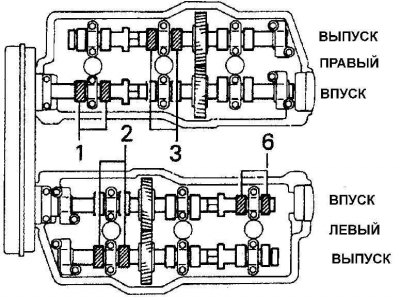
Fig. 2
On the 3VZ-FE engine, when setting the piston of the first cylinder to the top dead center in the compression stroke, measure the clearance of the valves marked with numbers.
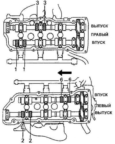
Fig. 3
On the 1MZ-FE V6 engine, when setting the piston of the first cylinder to the top dead center in the compression stroke, check the clearance of the valves indicated by numbers.
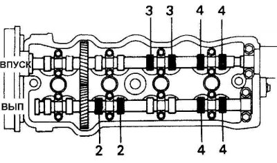
Fig. 4
On four-cylinder engines, rotate the crankshaft one full revolution, re-align the timing marks, and check the valve clearances on the remaining cylinders.
(The original publication can be found on the website www.toyotaman.ru)
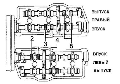
Fig. 5
On the 3VZ-FE V6 engine, after turning the engine crankshaft 240° from the top dead center position of the first cylinder in the compression stroke, check the clearance of the valves indicated by numbers.
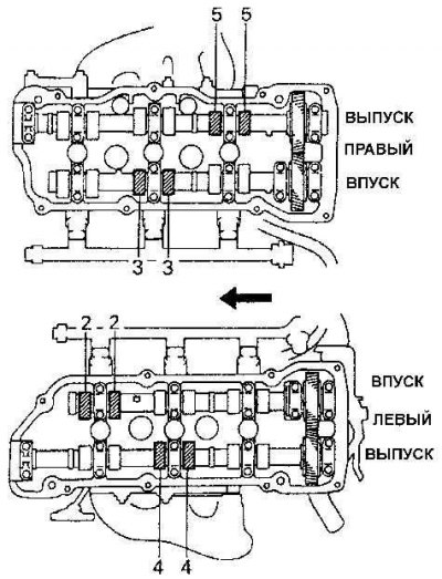
Fig. 6
On engine 1 MZ-FE V6, after turning the engine crankshaft 240° from the top dead center position of the first cylinder in the compression stroke, check the clearance of the valves indicated by numbers.
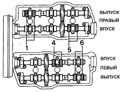
Fig. 7
On the 3VZ-FE V6 engine, turn the engine crankshaft an additional 240° and check the valve clearance on the remaining cylinders.
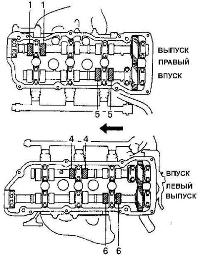
Fig. 8
On engine 1 MZ-FE V6, turn the engine crankshaft an additional 240° and check the valve clearance on the remaining cylinders.
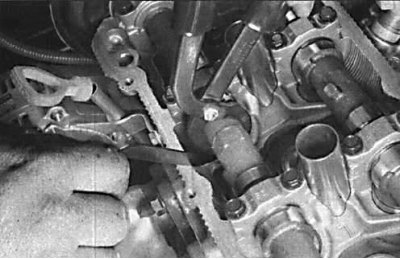
Using a special tool to press the valve tappet
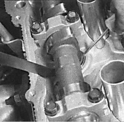
Fixing the valve tappet in the pressed position
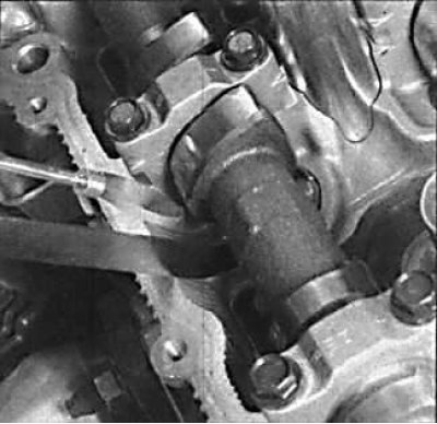
Removal the adjusting plate from the valve tappet
1. Remove the ground cable from the battery.
2. On a four-cylinder engine, disconnect the spark plug wires.
3. On V6 engines, drain the coolant from the cooling system, remove the air cleaner housing and any other components that prevent removal of the cylinder head cover.
4. Use compressed air to remove dirt from the spark plug locations so that it does not get into the cylinders after unscrewing the spark plugs. Unscrew the spark plugs.
5. Remove the cylinder head cover.
6. Set the piston of the first cylinder to the top dead center in the compression stroke.
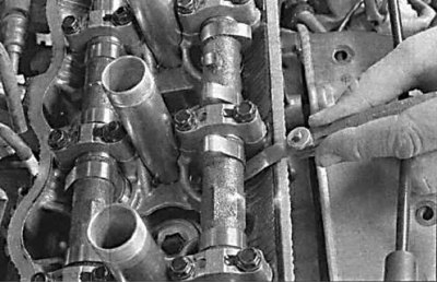
7. Using a feeler gauge blade, measure the valve clearances and record the values. (See Figures 1–3) 8. On four-cylinder engines, rotate the crankshaft one full revolution and re-align the timing marks. Check the valve clearances on the remaining cylinders (See Fig. 4). On four-cylinder engines, when the piston of the fourth cylinder is at top dead center in the compression stroke, check the clearances of the exhaust valves of cylinders No.2 and No.4 and the clearances of the intake valves of cylinders No.3 and No.4.
9. On V6 engines, rotate the crankshaft 240° clockwise and check the valve clearance shown in Fig. 5, 6. Then rotate the crankshaft another 240° and check the valve clearance on the remaining cylinders (See Fig. 7).
10. After measuring the valve clearances, turn the engine crankshaft to a position where the camshaft cam above the valve on which adjustment is required is positioned upward.
11. Turn the recess in the valve tappet toward the spark plug. Using the special tool, press the valve tappet down and lock the tappet in this position. Using tweezers or a magnet, remove the adjusting plate from the tappet (See the figures Using the special tool to press the valve tappet, Fixing the valve tappet in the pressed position, Removing the adjusting plate from the valve tappet).
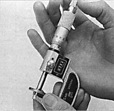
12. Measure the thickness of the adjusting plate with a micrometer. Use the following formula to determine the required thickness of the adjusting plate:
N = T + (A – V),
T – thickness of the old adjustment plate,
A – valve clearance,
N – thickness of the new adjustment plate,
V – required valve clearance.
12. Select the adjustment plate whose thickness is closest to the calculated one. Adjustment plates are available in thicknesses from 2.500 to 3.300 mm in 0.05 mm increments.
13. Install the valve tappet tool with the long jaw gripping the bottom edge of the tappet and the shorter jaw gripping the top edge of the tappet, press the tappet down by squeezing the handles of the tool and install the adjusting plate of the required thickness. Remove the adjusting plate installation tool and measure the valve clearance.
14. Similarly, replace the adjusting plates on the valves that require adjustment.
15. Install the spark plugs, cylinder head cover, high-voltage wires and other previously removed components.
Replacing the fuel tank cap gasket
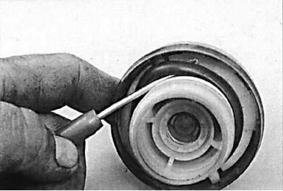
1. Remove the fuel filler cap and use a screwdriver to remove the old gasket from the groove in the cap.
2. Carefully install the new gasket into the groove of the cover.
3. Replace the fuel filler cap.
Checking the crankcase ventilation valve
The crankcase ventilation valve is located in the cylinder head cover.
1. Remove the hose from the valve and remove the PCV valve from the cover, then reconnect the hose.
2. With the engine idling, place your finger on the PCV valve and check for vacuum. If there is no vacuum, check the hose or valve.

3. Turn off the engine and remove the PCV valve from the hose. Blow out the valve from the cylinder head side. If air does not pass when blowing through the valve, replace the valve.