
Examination
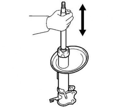
Pic. 4.46. Checking shock absorber travel
When pulling out and sinking the shock absorber rod, check that its stroke is smooth and there is no extraneous resistance or noise. If defective, replace shock absorber (pic. 4.46).
Installation
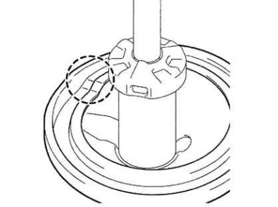
Pic. 4.47. Installing the Lower Spring Insulator
Install the lower spring insulator as shown in Figure 4.47.
Install the compression stroke stop on the stem.
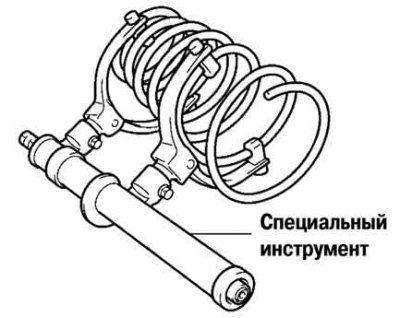
Pic. 4.48. Spring compression before installation
Using the special tool, compress the spring and install it on the strut (pic. 4.48).
Pic. 4.49. Proper installation of the top support cup
Establish the top support of a rack as it is shown in drawing 4.49, and temporarily tighten a fastening nut.
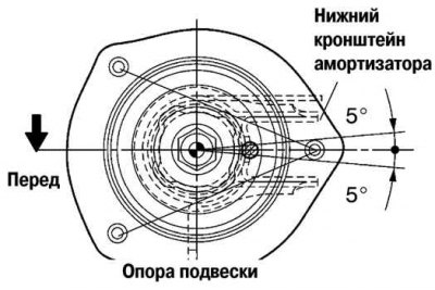
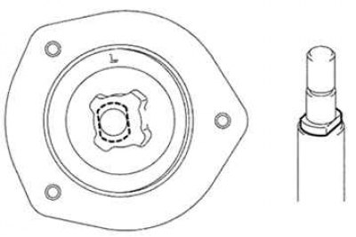
Pic. 4.50. Orientation of the cup of the upper rack support by marks
Orient the rack support cup as shown in Figure 4.50.
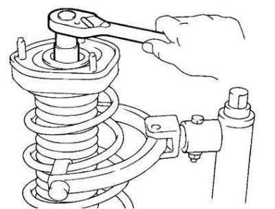
Pic. 4.51. Tightening the central nut of the upper rack support
Tighten the center nut of the upper strut mount without removing the special tool that compresses the shock absorber spring (pic. 4.51).
Tightening torque: 49 Nm.
Remove the special tool.
Tighten the 3 nuts securing the upper rack support.
Tightening torque: 39 Nm.
Note. After removing the special tool, check again that the upper support is correctly installed
Tighten the two mounting nuts on the underside of the shock strut.
Tightening torque: 255 Nm.
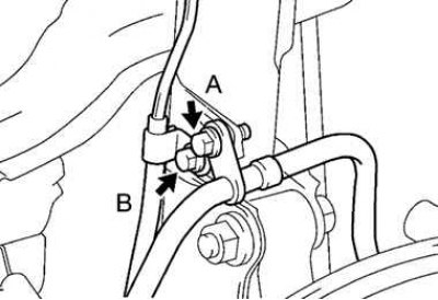
Pic. 4.52. The order of tightening the bolts of the holder of the brake hose and the wiring harness of the speed sensor (ABS)
Tighten the 2 bolts securing the brake hose holder and speed sensor harness (ABS). Tighten them in the order shown in Figure 4.52.
Torque:
- brake hose retainer bolt: 19 Nm;
- speed sensor wiring harness retainer bolt (ABS): 5.5 Nm.
Install other components in the reverse order of removal.
After installation, check the rear wheel alignment.