
Removing
Note: Installation is in reverse order of removal. After installation, check the rear wheel alignment and the operation of the speed sensors (ABS).
1. Jack up the car and remove the rear wheel.
- Tightening torque - 105 Nm
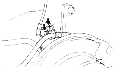
2. Remove two bolts, brake hose and speed sensor wiring harness (ABS) from the rack.
Torque:
- hose bolt - 30 Nm
- wire fastening bolt - 5.5 Nm
Front wheel drive models
All-wheel drive models
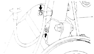
3. Turn away a bolt of fastening and remove the sensor of frequency of rotation (ABS).
Torque:
- 2WD - 8 Nm
- 4WD - 19.5 Nm
(2WD)
Remove the O-ring.
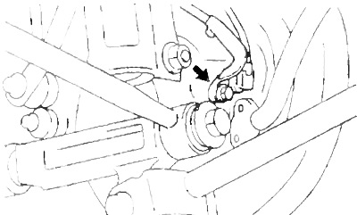
4. (Models with drum brakes) Disconnect the brake pipe from the wheel brake cylinder.
- Tightening torque - 15.5 Nm
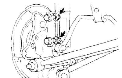
5. Disconnect the stabilizer link from the rear suspension strut.
- Tightening torque - 65 Nm
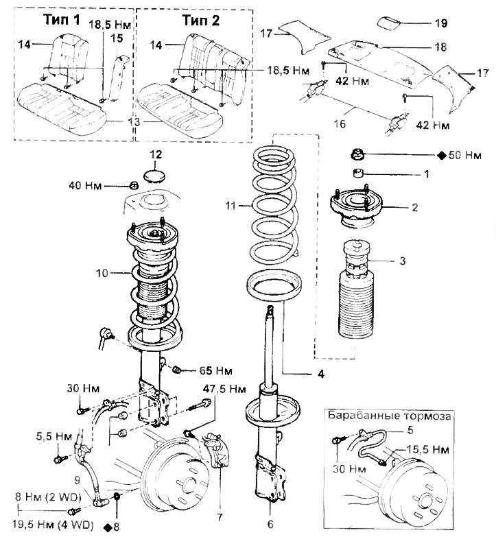
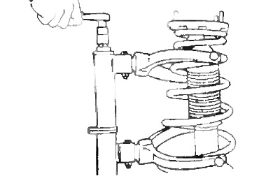
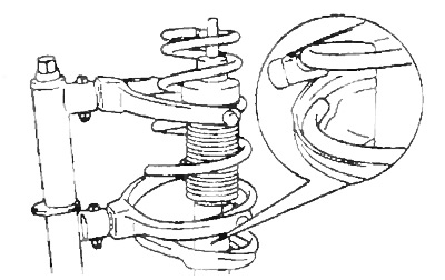
Rear suspension strut.
1 - bushing,
2 - top support of the rack,
3 - compression stroke limiter,
4 - lower vibration isolator,
5 - brake pipe,
6 - rear suspension strut,
7 - caliper assembly,
8 - gasket,
9 - speed sensor (ABS),
10 - rear suspension strut assembly,
11 - spring brake hose,
12 - plug,
13 - rear seat cushion,
14 - rear seat back,
15 - sidewall of the back of the rear seat,
16 - seat belt,
17 - rear pillar trim,
18 - rear shelf,
19 - additional brake light.
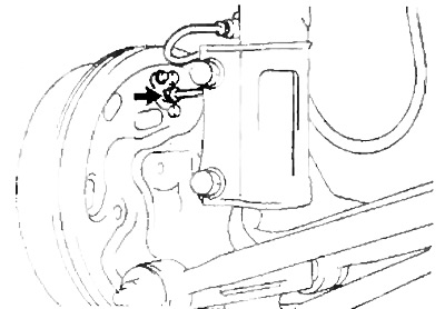
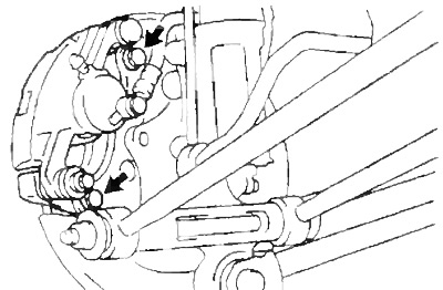
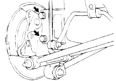
6. (Models with disc brakes)
Loosen the two bolts and remove the caliper assembly.
- Tightening torque - 47.5 Nm
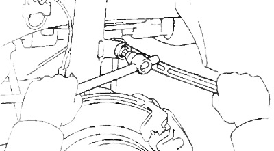
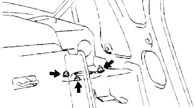
7. Loosen the two nuts on the underside of the rack.
- Tightening torque - 260 Nm
8. Remove a back of back sitting and a back shelf.
9. Turn away a bolt of fastening of a seat belt.
- Tightening torque - 42 Nm
10. Remove the rear suspension strut assembly.
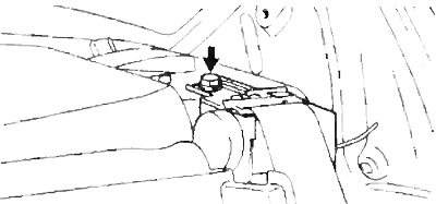
A) Remove the plug.
b) Loosen the nut located in the center of the upper rack support
Note: Do not remove the nut.
- Tightening torque - 50 Nm
V) Loosen the three nuts securing the top support.
- Tightening torque - 40 Nm
G) Remove two bolts and strut assembly.
Disassembly
1. Remove the spring.
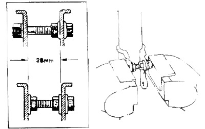
A) Install the bolt and two nuts on the bracket at the bottom of the upright as shown in the picture and secure it in a vise.
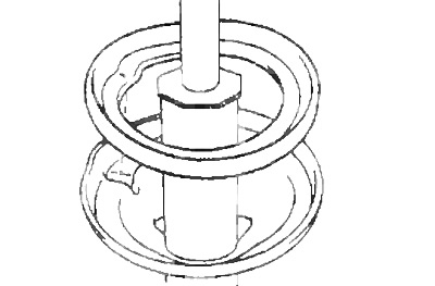
b) Using the special tool, compress the spring.
V) Loosen the nut located in the center of the upper rack support.
G) Remove: upper strut support, spring, compression stroke limiter, lower vibration isolator.
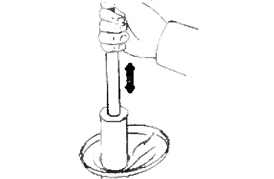
Shock absorber check
Pulling and sinking the shock absorber rod, check that its stroke is smooth and there is no extraneous resistance or noise.
Assembly
1. Install the lower vibration isolator.
2. Install the spring stop on the stem.
3. Install the spring.
A) Using the special tool, compress the spring.
b) Install the spring on the strut.
Note: Install the lower end of the spring into the groove in the lower strut seat.
4. Install the top post of the rack.
A) Install the upper strut support and temporarily tighten the new nut.
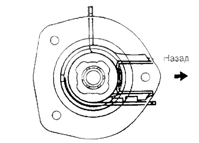
b) Install the rack support as shown in the illustration.
V) Remove the special tool.
Note: After removing the special tool, check that the top support is correctly installed.