
Vehicle checks
1. Check the intake and exhaust system.
A) Check for leaks and blockages between the air filter and the air duct, and between the air duct and the cylinder head. Replace defective elements if necessary. Eliminate any leaks in the connections.
2. Check the status of the systems and the absence of:
- parts deformations:
- foreign objects in the channels;
- cracks.
3. Check boost pressure.
A) Warm up the engine.
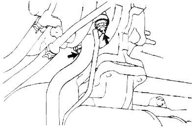
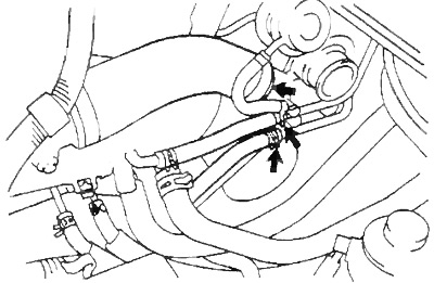
b) Install a pressure gauge in the gap in the hose connected to the intake manifold.
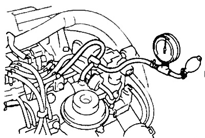
V) Disengage the clutch and depress the accelerator pedal sharply. Measure the boost pressure at an engine speed of 5100-5200 rpm.
- Pressure - 0.53-0.67 bar
If the pressure is less than the regulated one, check the tightness of the intake and exhaust systems. If the systems are normal, replace the turbocharger. If the pressure is more than the regulated one, check the condition of the vacuum hose of the bypass valve drive. If the hose is OK, replace the turbocharger.
4. Check compressor wheel rotation.
Removal and installation of a turbocharger
Note: The turbocharger is installed in the reverse order of removal. The tightening torques for nuts and bolts are shown in the figure "Removal and installation of a turbocharger". Use new gaskets when installing.
1. Drain the engine coolant.
2. Disconnect the wiring harness.
3. Disconnect the vacuum tubes.
4. Disconnect the air tube.
5. Remove heat shields.
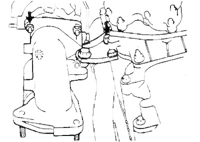
6. Remove the turbocharger bracket by removing the three bolts.
7. Turn away three bolts and remove a reception pipe.
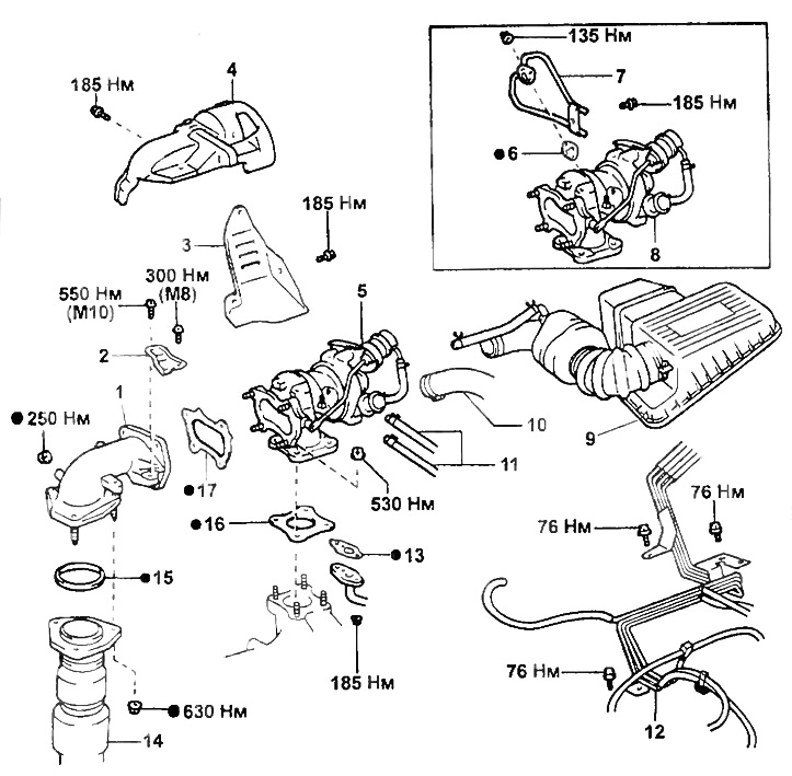
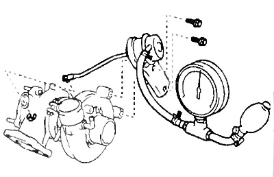
Removal and installation of a turbocharger.
1 - outlet pipe,
2 - turbocharger bracket,
3 - heat shield No. 2,
4 - heat shield No. 1,
5-, 8 - turbocharger assembly,
6-, 13-, 15-, 16-, 17 - gasket,
7 - coolant supply pipes,
9 - air filter cover with resonator,
10 - air hose No. 1,
11 - coolant supply hoses,
12 - vacuum tubes,
14 - receiving pipe.
8. Turn away two bolts and remove an arm of a turbocharger. Remove the outlet pipe by unscrewing the four bolts
9. Turn away two bolts and disconnect a tube of drain of oil.
10. Disconnect coolant supply hoses and #1 air hose.
11. Turn away four nuts, remove a turbocharger in gathering and a lining.
12. Turn away two nuts, disconnect tubes of giving of a cooling liquid and remove a lining.
Turbocharger check
1. Check wheel rotation. Make sure the wheels turn smoothly.
If the wheels do not rotate or rotate with resistance, replace the turbocharger.
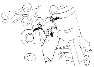
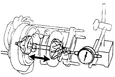
2. Check the axial clearance of the compressor shaft.
Install the dial indicator on the compressor side, moving the turbine wheel by hand, measure the axial clearance.
- Axial clearance - no more than 0.11 mm
If the axial clearance is out of range, replace the turbocharger.
3. Check the radial clearance of the compressor shaft.
A) Through the oil drain hole from the turbocharger, install the indicator on the compressor shaft.
b) While moving the shaft in the radial direction, measure the radial clearance.
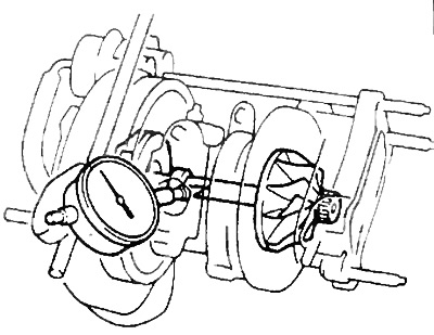
- Radial clearance - no more than 0.16 mm
If the radial clearance is out of tolerance, replace the turbocharger.
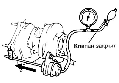
4. Check the operation of the actuator drive
A) Disconnect the actuator diaphragm hose
b) Pressurize the diaphragm to approximately 0.92-0.97 bar: the actuator stem must move and the valve must open.
Warning: never pressurize the diaphragm more than 1.4 bar.
Checking the actuator
1. If necessary, remove the actuator.
A) Disconnect the air hose.
b) Remove the two bolts securing the actuator to the turbocharger housing.
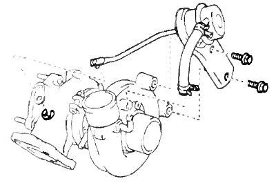
V) Remove the retaining ring that secures the stem to the valve and remove the actuator.
2. Adjust the stroke of the actuator rod.
Note: Adjustment is carried out on the installed actuator.
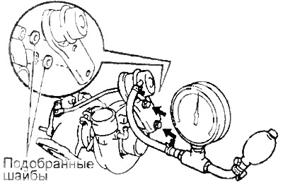
A) Install a dial indicator and apply 0.88 bar pressure to the actuator and measure the stroke.
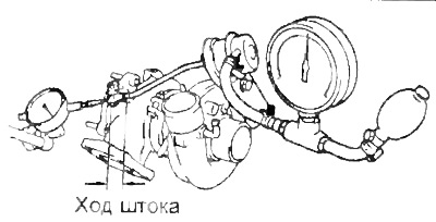
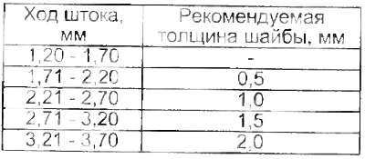
b) Based on the measured stroke value, select the required washer thickness from the table below.
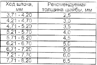
Note:
- A set of washers of various thicknesses can be used to obtain the required thickness (0.5; 1.0; 2.0; 3.0 mm).
- Use the same set of washers of varying thicknesses between the actuator and housing
- If the required washer thickness is greater than 3.5 mm. then replace the actuator mounting bolts.
V) If necessary, install new washers and bolts, apply a pressure of 1.09 bar.
- Tightening torque - 19 Nm
G) Apply 0.88 bar pressure to the actuator and recheck the stroke.
- Nominal value - 1.20 - 1.70 mm
Replace washers if necessary.
4. Connect the air hose.
5. Check boost pressure (see "Vehicle checks").