
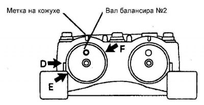
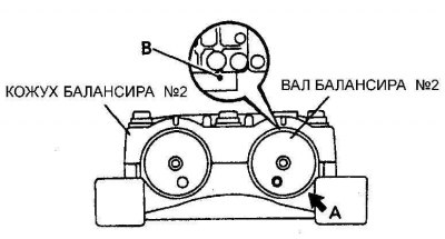
The initial position of the marks of the balancer No. 2 | 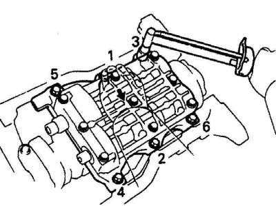
The sequence of tightening the bolts of the balancer assembly |
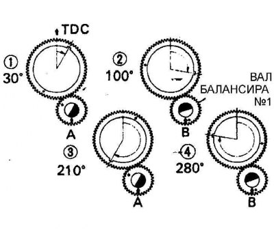
Positions in which it is necessary to measure the backlash of the shaft of the balancer No. 1 in relation to the crankshaft | 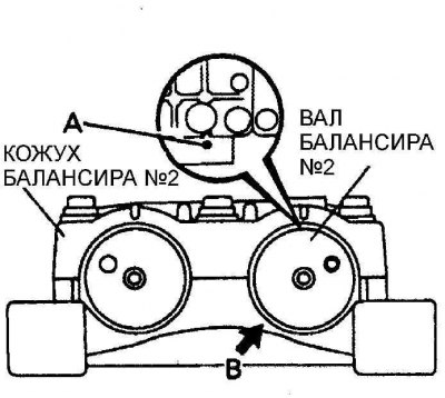
Determination of the backlash of the shaft of the balancer No. 1 |
The second and fourth position for measuring the backlash of the shaft of the balancer No. 1 | 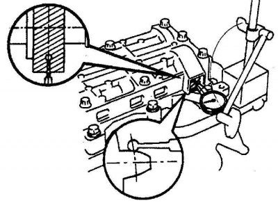
Installing a dial indicator to measure balancer shaft backlash |
1. Turn the crankshaft of the engine so that the piston of the first cylinder is at top dead center.
2. Set the #2 balancer shaft to the position shown in Figure Initial position of #2 balancer marks.
3. Install the balancer assembly on the engine block and secure with bolts by tightening them in a certain sequence (see fig. The sequence of tightening the bolts of the balancer assembly).
4. Since the play between the crankshaft and the No. 1 balancer shaft changes with rotation, measure the play at the four positions indicated (see fig. Positions in which it is necessary to measure the backlash of the shaft of the balancer No. 1 in relation to the crankshaft).
5. Turn the engine crankshaft a few revolutions and set to a position in which the piston of the first cylinder is at top dead center. Check that the marks on the balancer assembly are re-aligned.
6. Turn the crankshaft of the engine clockwise until the mark of the balancer shaft No. 1 is aligned with the pointer (see fig. Determination of the backlash of the shaft of the balancer No. 1).
7. Install a dial indicator on the #1 balancer shaft gear teeth (see fig. Installing a dial indicator to measure balancer shaft backlash). Applying a slight effort, turn the shaft of the balancer No. 1 to the sides and determine the play.
8. Remove the dial indicator and rotate the engine crankshaft clockwise until the mark D on the balancer shaft No. 1 is aligned with the pointer (see fig. The second and fourth position for measuring the backlash of the shaft of the balancer No. 1). Install a dial gauge and measure the backlash.
9. If the amount of play differs from the required values, install a gasket between the balancer assembly and the cylinder block of the required thickness.