
Check the condition of the friction surface of the flywheel for cracks, burn marks and surface wear.
Check the condition of the friction linings of the clutch driven disk and if they have traces of oil or mechanical damage, replace the driven disk.
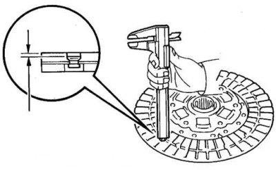
Pic. 3.35. Measuring the friction linings of the clutch disc
Check the thickness of the clutch disc linings with a vernier caliper. Linings should protrude above the rivet heads by at least 0.3 mm (pic. 3.35).
If the thickness of the lining is less than acceptable or the heads of the rivets are close to the working surface, replace them or the clutch disc. Check that the springs are not broken or cracked. Check the splines in the clutch disc hub for wear.
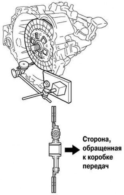
Pic. 3.36. Installing the clutch disc on the gearbox shaft
Install the clutch disc on the gearbox shaft (pic. 3.36).
The clutch disc should slide easily and smoothly on the splines of the gearbox input shaft.
Attention! If the clutch disc is being replaced, the clutch release bearing must also be replaced.
Using a dial gauge, check clutch disc runout.
Minimum runout: 0.8 mm.
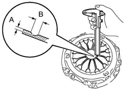
Pic. 3.37. Measurement of the depth and width of the wear of the petals of the diaphragm spring
Using a vernier caliper, check the depth and width of the diaphragm spring petals for wear (pic. 3.37).
Maximum:
- A (depth): 0.5 mm;
- B (width): 6.0 mm.
Note. Slight damage to the friction surface can be removed with fine sandpaper, but if there is any doubt about the condition of the pressure plate, it must be replaced with a new one.
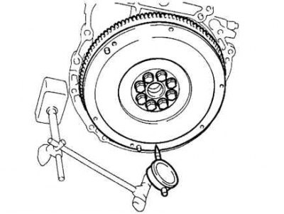
Pic. 3.38. Flywheel Runout Measurement
Using a dial gauge, check flywheel runout (pic. 3.38).
Maximum runout: 0.1 mm.
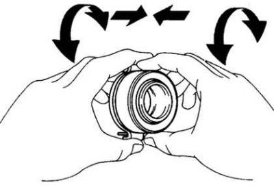
Pic. 3.39. Checking the clutch release bearing
Rotate the clutch release bearing by hand, applying force in the axial direction, check the clutch release bearing (pic. 3.39).
Note. The bearing is lubricated for life, so no additional lubrication is required.
Note. If necessary, replace the clutch release bearing.