
Note (A540N): in case of simultaneous failure of two speed sensors (front and rear output shafts of the gearbox) no fault code will appear and the self-diagnosis system will not work. However, in the selector position "D", the movement will be possible only in first gear, regardless of the vehicle speed.
Code 42 (A140E): vehicle speed sensor circuit
1. Check the speedometer (see section "electrical equipment"). Replace faulty speedometer.
2. Measure the voltage between the terminals "SPD" And "E1" connector of the automatic transmission and engine control unit. If the voltage is correct, replace the control unit.
3. Check the vehicle speed sensor. Replace faulty sensor.
4. Check up a combination of devices. Replace faulty instrument cluster.
5. Check up a plait of wires between the block of management and a combination of devices.
Code 44 (A540N): rear output shaft speed sensor circuit
1. Measure the conductivity between the terminals "RR+" And "RR-" connector of the automatic transmission and engine control unit. If there is continuity, then replace the automatic transmission and engine control unit.
2. Check the transaxle rear output shaft speed sensor Replace the faulty sensor.
3. Check the wiring harness between the control unit and the speed sensor.
Code 61: Gearbox front output speed sensor circuit
1. Measure the conductivity between the terminals "FR+" And "FR-" connector of the automatic transmission and engine control unit. If there is continuity, then replace the automatic transmission and engine control unit.
2. Check the transaxle front output speed sensor. Replace faulty sensor.
3. Check the wiring harness between the control unit and the speed sensor.
Code 62: Solenoid Valve Circuit #1
1. Measure the resistance of solenoid valve No. 1 at the connector of the automatic transmission and engine control unit. If the resistance corresponds to the nominal, then replace the automatic transmission and engine control unit.
2. Remove the oil pan and measure the resistance between solenoid valve connector Ne1 and "earth". If resistance is not within specification, replace solenoid valve #1.
- Rated resistance - 11 - 15 Ohm
3. Check the wiring harness between the No. 1 solenoid valve and the automatic transmission control unit and the engine.
Code 63: Solenoid Valve Circuit #2
1. Measure the resistance of solenoid valve No. 2 at the connector of the automatic transmission and engine control unit. If the resistance is correct, then replace the automatic transmission and engine control unit.
2. Remove the oil pan and measure the resistance between the N92 solenoid valve connector and "earth". If the resistance is not within specification, replace valve #2.
- Rated resistance - 11 - 15 Ohm
3. Check the wiring harness between the No. 2 solenoid valve and the automatic transmission control unit and the engine.
Code 64: Torque Converter Clutch Control Solenoid Circuit
1. Measure the resistance of the solenoid valve at the automatic transmission and engine control unit connector. If the resistance is normal, replace the automatic transmission and engine control unit.
2. Remove the oil pan and measure the resistance between the torque converter clutch control solenoid valve connector and "earth". If the resistance is not correct, replace the blocking solenoid valve.
- Rated resistance - 11-15 Ohm
3. Check the wiring between the solenoid valve and the automatic transmission control unit and the engine.
Code 73 (A540N): center differential lock solenoid valve circuit
1. Measure the resistance of the solenoid valve at the automatic transmission and engine control unit connector. If the resistance is within specification, replace the automatic transmission control unit.
2. Remove the oil pan and measure the resistance between the solenoid valve connector and "earth". If the resistance is not within specification, replace the solenoid valve.
- Rated resistance - 11-15 Ohm
3. Check the wiring harness between the solenoid valve and the automatic transmission control unit and the engine.
Resetting trouble codes
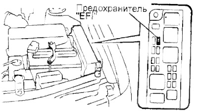
1. After the repair, clear the memory of the automatic transmission control unit and the engine from the fault codes that are stored there. To do this, remove the fuse "EFI" for 10 seconds or more depending on the ambient temperature (the lower the temperature, the longer) with the ignition off.
Attention:
- - To reset the trouble codes, disconnect the negative battery terminal for a while. In this case, the contents of the memory of control units of other systems will be lost.
- - To reset the trouble codes, disconnect the automatic transmission and engine control unit connector.
- - If the fault code has not been reset, then it will be stored in the memory of the control unit, and will appear during subsequent diagnostics.
2. After resetting the codes, check that the flashing of the overdrive indicator should correspond to the normal condition of the gearbox.
Gear shift check
Note: This check allows you to determine if the cause of the malfunction is an electrical or mechanical problem in the transmission.
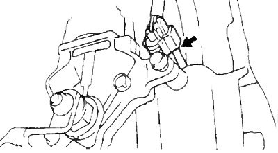
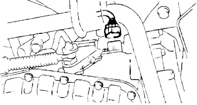
1. Disconnect the solenoid valve block connector.
A140E
A540H
2. Gear shifting must occur in accordance with the table below "Transmission operating modes in case of normal operation of solenoid valves (solenoids) and failure of one or two of them".
Table. Transmission operating modes in case of normal operation of solenoid valves (solenoids) and failure of one or two of them
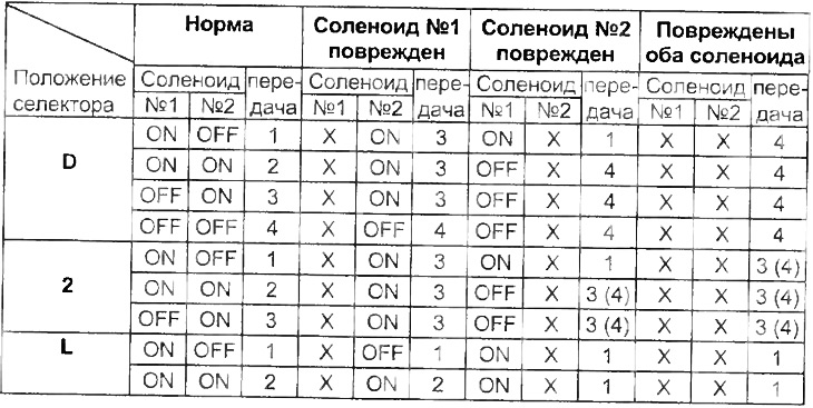
Note: PX marks" indicate a malfunction. () - for A540N.
Note:
- If on the ranges "L", "2" And "D" it is difficult to determine the number of the engaged gear, then carry out the following test:
- While driving, move the selector to positions "L", "2" And "0". Gear shifting must correspond to the position of the lever.
- If a deviation occurs during the shift process, then the fault is in the gearbox itself.
3. Connect the solenoid valve block connector.
4. Reset trouble codes.
Checking the voltage at the output "TT"
1. Checking the signal from the throttle position sensor.
A) Turn on the ignition. Do not start the engine.
b) Connect a voltmeter to the diagnostic connector "TT" And "E1".
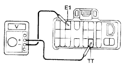
Note: Use a voltmeter with an internal resistance of at least 10 kΩ/V.
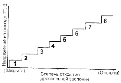
V) While gently depressing the accelerator pedal, check the voltage change. If the voltage does not change as shown in the figure, then the sensor or its circuit is faulty.
2. Checking the brake light switch circuit.
A) Press all the way down on the accelerator pedal. Contact voltage "TT" should be the specified value.
- Voltage - 8 V
b) Depress the brake pedal and check the voltage at the CT terminal".
Voltage:
- brake pedal pressed - 0.5 V
- brake pedal released - 7.6-8.7 V
V) If there is a deviation from the specified voltages, then there is a malfunction in the brake light switch circuit.
3. Checking the moments of upshifts.
A) Warm up the engine to a coolant temperature of 80°C.
b) Set the overdrive switch to "ON".
V) Set the selector to position "D".
G) During the road test (speed about 10 km/h) check the voltage change at the output "TT" during upshifts.
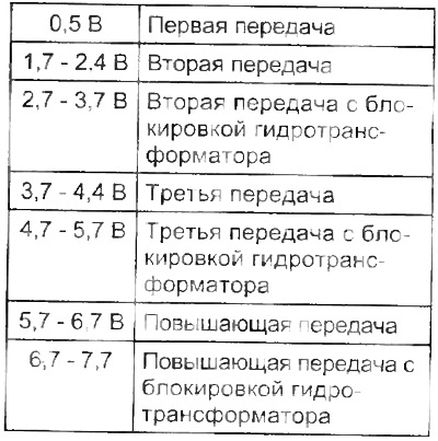
Note: Shifting to the next gear can be detected by a slight jolt or change in engine speed.
d) If the output voltage "TT" does not match the specified, then check the output circuit "TT".