
General information
1. The self-diagnosis function is built into the automatic transmission electronic control unit. With the help of the overdrive off indicator, the system can warn the driver of a malfunction in the automatic transmission. The fault code that has occurred can be determined using the same indicator.
Warning: Warning signals and fault codes can only be read when the overdrive switch is in the "ON". If the switch is in position "OFF", the indicator lamp lights up without blinking.
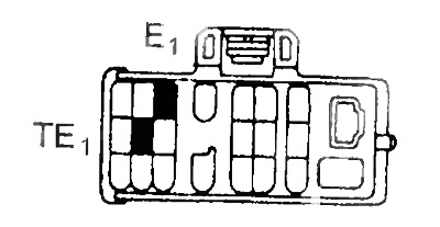
A) Fault codes can be read by the number of flashes of the overdrive indicator, to do this, short the leads "TE1" And "E1" diagnostic socket.
V) The diagnostic system does not determine the failure of the throttle position sensor and brake light switch, but they can be checked by checking the voltage at the output "TT" diagnostic socket.
2. The fault code is stored in the memory of the control unit even after the engine is turned off. Clearing the memory of the control unit (reset codes after repair) either by turning off the ignition and disconnecting the fuse "EFI", or by disconnecting the connector of the automatic transmission and engine control unit.
Caution: Low battery voltage may cause diagnostic failure. Therefore, before starting diagnostics, check the battery.
Checking the overdrive off indicator
1. Turn on the ignition.
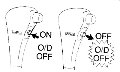
2. The indicator should be on when the overdrive switch is in the 'OFF' position.
3. Move the overdrive switch to the "ON": The indicator should turn off. If the indicator flashes, then this is a sign of a malfunction in the electrical part of the control system.
Reading trouble codes
1. Turn on the ignition and set the overdrive switch to "ON".
Attention: do not start the engine.
2. Short the leads "TE1" And "E1" diagnostic socket.
3. Read and determine the fault code by the number of blinks of the indicator.
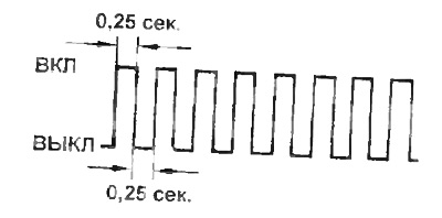
A) If there are two flashes per second, then the system is working normally.
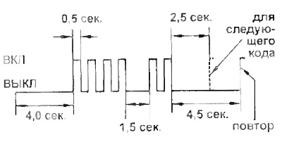
b) If there is one flash per second, then there is a malfunction in the system. The code consists of two digits, the first digit is determined by the initial series of flashes, followed by a 1.5 second pause and a second series of flashes, which corresponds to the second digit of the code. If there are two or more fault codes, then there will be a 2.5 second pause between them.
Attention: if there are several fault codes, the smallest code is always displayed first. and then the rest of the codes in ascending order.
4. Disconnect the pins "TE1" And "E1".
Table. Fault codes. A140E.
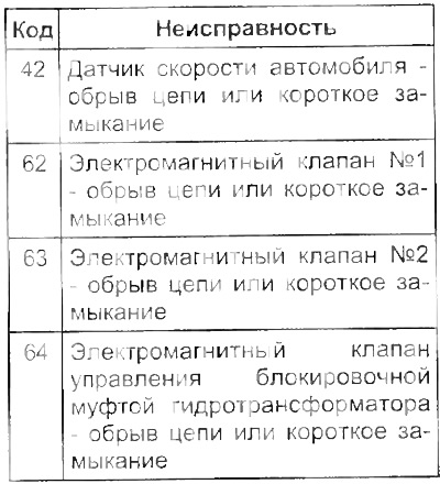
Note: codes 62, 63, 64, 68 indicate a malfunction in the electrical part of the solenoid valves. Malfunctions in the mechanical part, such as valve sticking, are not recorded by the self-diagnosis system.
A540N.
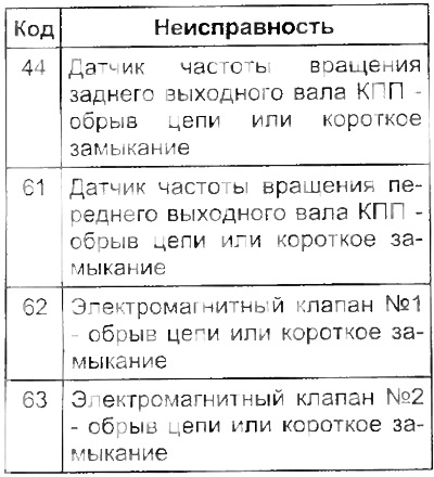
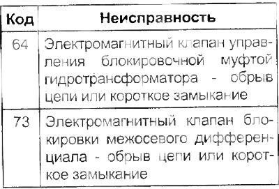
Note: Codes 62, 63, 64 73 or 77 indicate an electrical problem with the solenoid valves. Malfunctions in the mechanical part, such as valve sticking, are not fixed by the self-diagnosis system.