
Generator parts
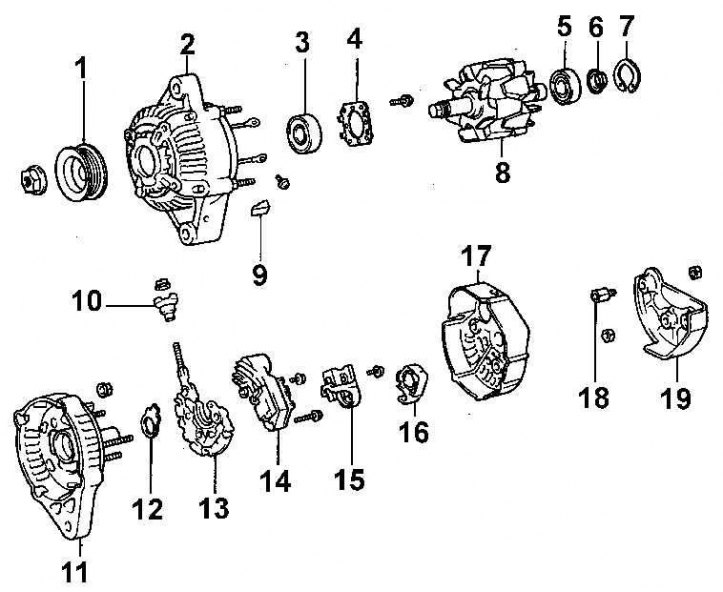
1 - pulley; 2 - front cover; 3 - bearing; 4 - bearing retainer; 5 - bearing; 6 - bearing cover; 7 - retaining ring; 8 - rotor; 9 - rubber insulator; 10 - insulator; 11 – back cover; 12 - insulating plate; 13 - holder; 14 - voltage regulator; 15 - brush holder; 16 – brush holder cover; 17 - rear casing; 18 - bushings; 19 - rear casing.
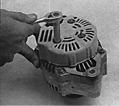
1. Remove the generator from the engine.
 | 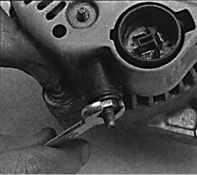 |
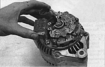
2. Unscrew the three nuts securing the rear casing of the generator and the nut of terminal B and remove the rear casing from the generator.
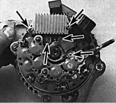
3. Unscrew the 5 screws securing the voltage regulator and brush holder.
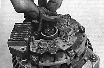 |  |
4. Remove the voltage regulator with brush holder from the back of the generator.
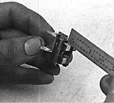
5. Using a ruler, check the protrusion of the brushes from the brush holder.
6. Check that the brushes move smoothly and without sticking in the brush holder.
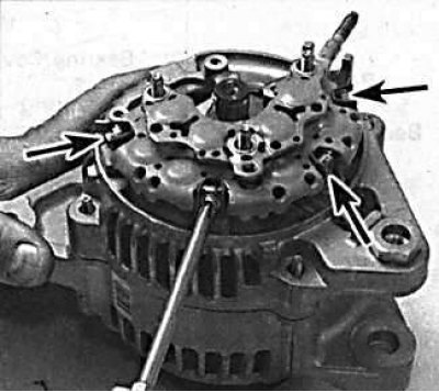
7. Unscrew the screws and remove the diode block from the generator.
8. Apply alignment marks to the front and rear covers of the generator.
9. Unscrew the fastening nut and remove the pulley from the rotor shaft.
10. Remove the four nuts securing the front and rear covers. Remove the back cover from the generator.
11. Remove the lock washer and remove the rotor from the front cover.
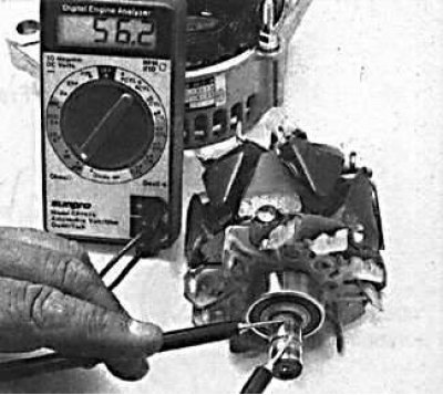 | 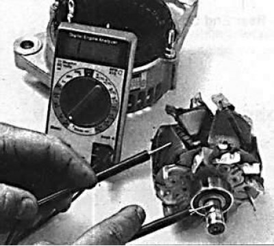 |
12. Using an ohmmeter, check the resistance between the alternator slip rings, which should be between 2 and 4 ohms. Check the resistance between the alternator slip rings and the alternator rotor. In this case, the resistance should be equal to infinity.
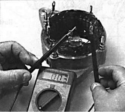
13. Using an ohmmeter, check the resistance of the stator windings.
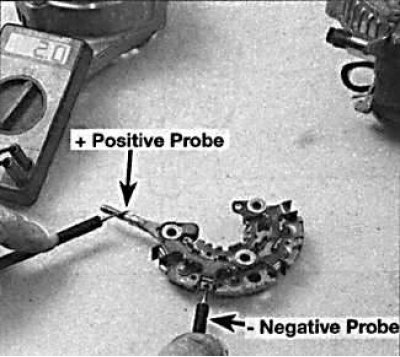 | 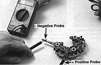 |
14. Check the condition of the diodes by connecting the ohmmeter probes to the diode, determine the resistance, then swap the probes and re-determine the diode resistance. In one case, the resistance should be low, and in the other case, it should be infinity.
15. The generator is assembled in the reverse order of disassembly.
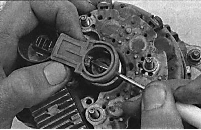
16. When installing the brush holder, use a small screwdriver to press the brushes into the brush holder housing.