
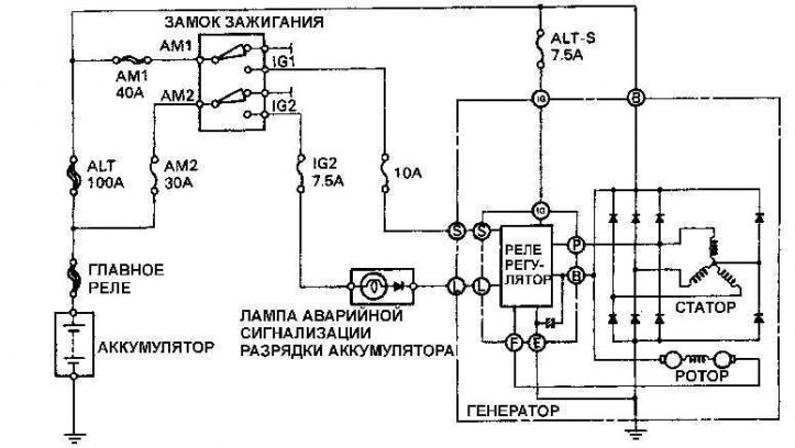
Electrical diagram of the charging system
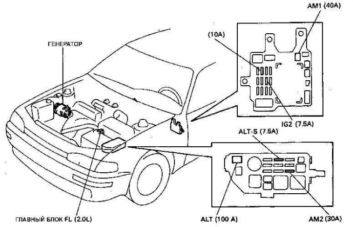
The location of the elements of the charging system on the car
The charging system includes a generator, voltage regulator, load indicator, battery, fuses and electrical wires.
If the battery charging control lamp does not light when the ignition is turned on, check the wiring connection to the generator and the integrity of the control lamp. If the lamp still does not light, check the electrical circuit from the generator to the lamp. If all electrical circuits are working, then the generator is faulty and should be replaced or repaired.
If the battery warning light comes on while the engine is running, stop the engine and check the condition and tension of the alternator drive belt and the wiring to the alternator.
The voltage regulator can be tested as follows:
1. Connect a voltmeter to the battery terminals and start the engine.
2. Increase the engine speed until the voltmeter reading stabilizes, which should show from 12 to 13 V, but not more than 14 V.
3. Turn on the maximum number of electrical consumers (headlights, rear window defroster, heater fan). In this case, the voltage generated by the generator with a voltage regulator should be in the range from 13 to 14 V.
4. If the voltage is out of specification, worn alternator brushes, a weak brush spring, a faulty voltage regulator, a faulty diode, a broken stator winding, or defective rotor slip rings may be the cause.
5. If the resistance differs from the required values, replace the ignition distributor.