
- make sure that there is no damage or deformation of the body in the headlight area;
- fill the fuel tank;
- make sure that the oil level is correct;
- make sure that the coolant level is correct;
- bring the pressure in the tires to normal;
- place the spare wheel, tool and jack in their original places;
- remove cargo from the trunk;
- put a person of average weight in the driver's seat (75 kg).
Preparing to adjust the headlights (using the screen)
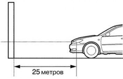
Pic. 1.56. Vehicle installation diagram in preparation for headlight adjustment
1. Prepare the vehicle as follows:
- park the vehicle in a room where it is dark enough to clearly see the edge of the headlight beams. The headlight beam boundary is a distinct line below which headlight beams are visible and above which they are absent (pic. 1.56);
- place the vehicle at an angle of 90°to the wall;
- the distance from the vehicle to the wall should be 25 m (from the center of the headlight bulb);
- place the vehicle on a horizontal surface;
- rock the vehicle up and down to set the suspensions.
Attention! Distance 25m between vehicle (from the center of the headlight bulb) and the wall is necessary to properly control the direction of the headlight beams. If this is not possible, ensure a distance of exactly 3 m for checking and adjustment. (The area of the light spots of the headlights changes with a change in distance, so you must follow the instructions in Figure 1.56)
2. Prepare a sheet of thick white paper (approximately 2 m (height) x 4 m (width)), to use it as a screen.
3. Draw a vertical line in the center of the screen (V-line).
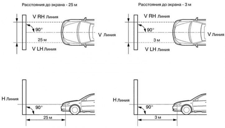
Pic. 1.57. Screen installation diagram
4. Install the screen as shown in Figure 1.57.
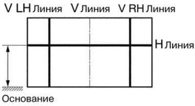
Pic. 1.58. Screen baseline diagram
5. Draw baselines on the screen (line H, V Left, V Right), as shown in Figure 1.58.
Baselines for «low beam check» and «high beam test» are different.
Mark the centers of the headlight bulbs on the screen. If the position of the centers of the lamps cannot be determined from the marks on the headlight, be guided by the centers of the lamps of the headlight or the name of the manufacturer printed on the headlamp.
1. H line (headlight height): Draw a horizontal line across the screen so that it passes through the marked lamp center marks. Line H must run at the same height as the dipped beam center marks.
2. Line V Left, V Right (left center marks (LH) and right (RH) lamps): Draw two vertical lines so that they intersect line H at the points where the dipped beam center marks are made.
Headlight adjustment check
1. Close the headlamp or disconnect the appropriate electrical connector to prevent the light from the headlamp that is not currently being tested from interfering with the headlamp whose adjustment is being tested.
Attention! Do not keep headlight closed for more than 3 minutes. The headlight lens is made of a synthetic polymer and can easily melt or be damaged by heat.
When checking the high beam lamps, cover the low beam lamp or disconnect the corresponding connector.
2. Start the engine. In this case, the engine crankshaft speed should be at least 1500 min–1.
3. Set the headlight range control switch to position 0 (zero).
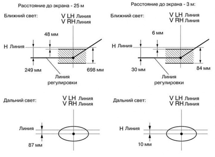
Pic. 1.59. Scheme for adjusting the boundaries of the light spots of the headlights
4. Turn on the headlight and make sure that the border of the light spots of the headlights falls into the area shown in Figure 1.59.
The adjustment data is shown below.
The distance to the screen is 25 m.
headlamp beam edge 48 to 696 mm below line H for dipped beam.
The distance to the screen is 3 m.
headlamp beam edge 6 mm to 84 mm below line H for dipped beam.
The distance to the screen is 25 m.
headlamp beam edge 249 mm below line H for dipped beam.
The distance to the screen is 3 m.
Headlight beam boundary 30 mm below line Hc for dipped beam.
Since the low beam and high beam are combined in the headlight, if the low beam is adjusted correctly, then the high beam must also be adjusted correctly. However, check both headlights to make sure the adjustment is correct.
Headlight adjustment
1. Adjust the light beam in the vertical direction:
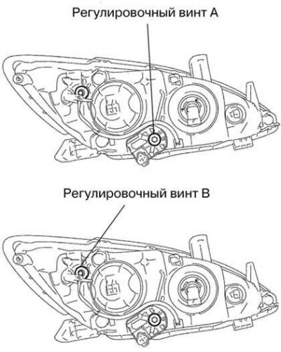
Pic. 1.60. headlight adjusting screws
Adjust the light beam of the headlight by turning the adjusting screw A with a screwdriver (pic. 1.60);
Attention! The final turn of the adjusting screw must be done in a clockwise direction. If the screw is over-tightened, loosen and then retighten it so that the final turn of the screw is in a clockwise direction.
- adjust the dipped beam;
- The light beam of the headlight rises when the adjusting screw is turned clockwise, and moves down when the screw is turned counterclockwise.
2. Adjust the light beam in the horizontal direction: adjust the headlight beam by turning the adjusting screw B with a screwdriver (pic. 1.60).
Table 1.4. Headlight adjustment examples
| Car loading status | Disc position |
| Driver only | 0 |
| Driver + front passenger | 0 |
| All passengers (including the driver) | 2 |
| All passengers (including the driver) + full trunk load | 4 |
| Driver + full trunk load | 5 |