
Examination
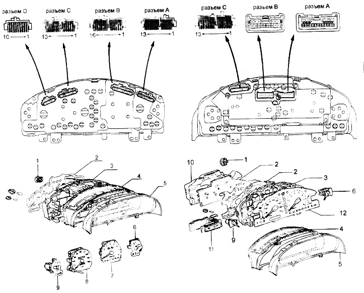
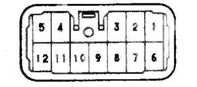
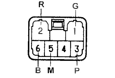
Instrument combination.
1 - warning buzzer when reversing,
2 - instrument cluster board,
3 - body,
4 - instrument cluster or instrument cluster visor,
5 - glass,
6 - coolant temperature gauge,
7 - tachometer,
8 - speedometer,
9 - fuel gauge,
10 - back cover,
11 - electronic unit of the mileage counter,
12 - instrument cluster panel.
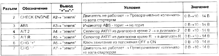
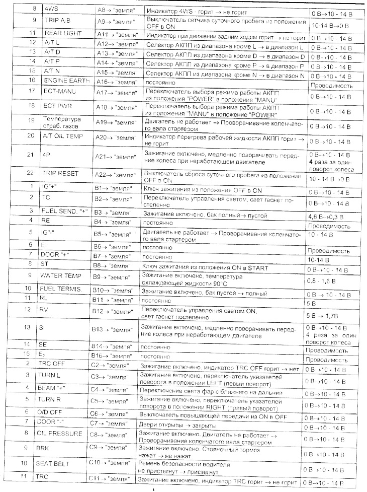
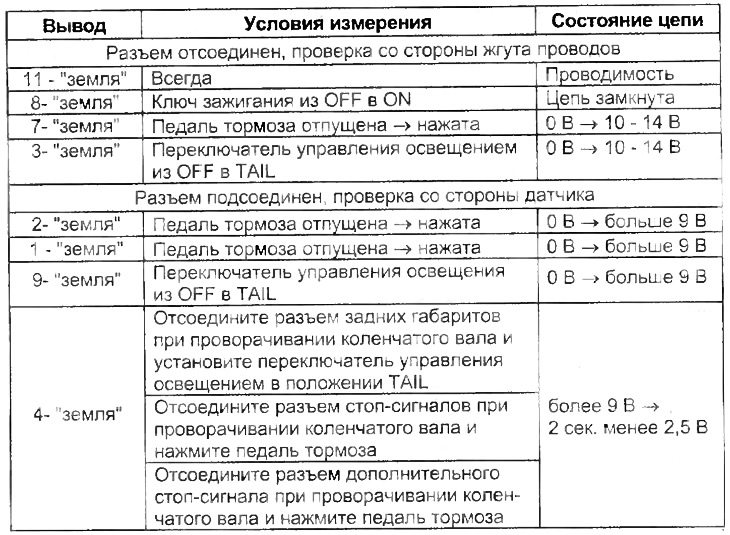
Instrument Cluster Circuit Check Table
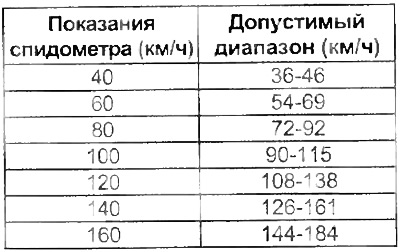
Checking the speedometer (analog panel)
1. Connect the tester and compare the readings of the tester and the speedometer.
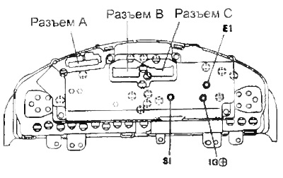
Checking the speedometer (analog-digital instrument cluster)
1. Checking the signal.
A) Remove the instrument cluster assembly.
b) Loosen 4 screws and remove the bottom case.
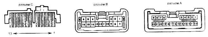
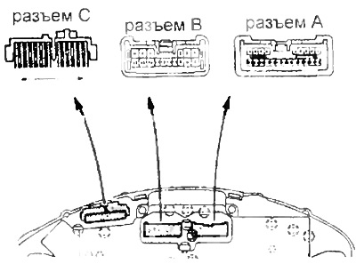
V) Connect connectors A, B and C.
G) Check continuity and voltage between terminals and "earth" according to the table "speedometer check (analog-digital instrument cluster) ".
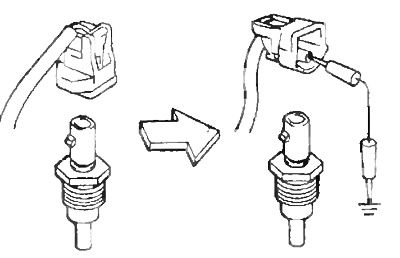
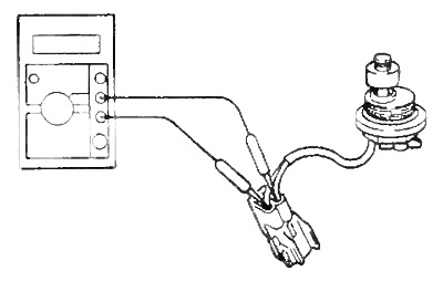
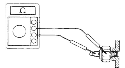
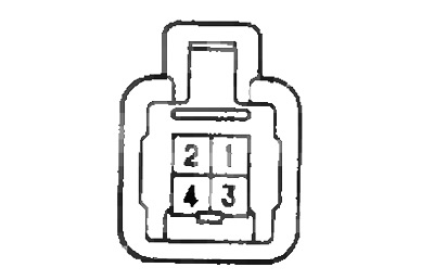
Checking the speedometer sensor
1. Checking work.
A) Remove the speed sensor.
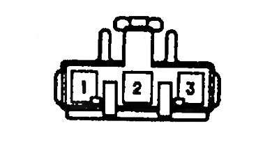
b) Connect the battery to the terminals "1" (+) And "2" (-).
V) Turn the shaft slowly and check for voltage between the terminals "2" And "3".
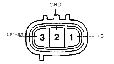
G) Check that in one revolution of the sensor shaft the voltage changes 4 times (appears and disappears).
If the operation is not as described, replace the sensor.
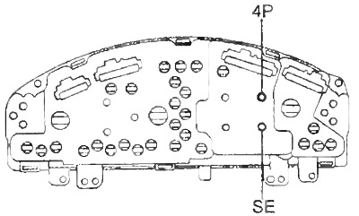
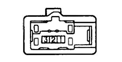
Checking the speedometer sensor (inside the instrument cluster)
Note: the test is carried out with the ignition on and the connector connected.
1. Checking work.
A) Disconnect the speed sensor.
b) Turn the shaft slowly and check for voltage between the terminals "3" (4R) connector B on the back of the instrument cluster and "4" (SE) connector A, as well as between the outputs of the speedometer "4P" And "SE" (analog instrument cluster)
V) Turn the shaft slowly and check for voltage between the terminals "21" (4R) connector A on the back of the instrument cluster and 14 (SE) connector B (analog-digital instrument cluster).
analog
G) Check that in one revolution of the sensor shaft the voltage changes 4 times (appears and disappears).
analog-digital
Checking the tachometer
Analog instrument cluster
1. Connect a calibration tachometer and start the engine.
Note: Reverse polarity when connecting a tachometer will damage the transistors and diodes.
2. Compare the readings of the calibration and standard tachometers.
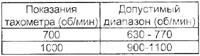
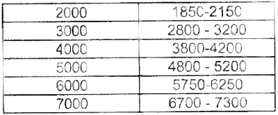
If the error limit is exceeded, replace the tachometer
Analog/Digital Instrument Cluster
1. Checking the signal.
A) Remove the instrument cluster assembly.
b) Loosen 4 screws and remove the bottom case.
V) Connect connectors A, B and C.
G) Check continuity and voltage between terminals and "earth" according to the table "Checking the tachometer" (analog-digital instrument cluster).
Checking the pointer coolant temperature sensor
1. Checking work.
A) Disconnect the coolant temperature sensor indicator connector.
b) Turn the ignition on and make sure the arrow is in position "WITH".
V) From the position specified in paragraph (b), short the connector lead to "earth". Make sure the arrow is in position "H".
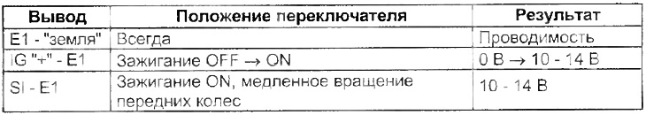
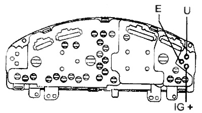
Checking the speedometer (analog-digital instrument cluster)
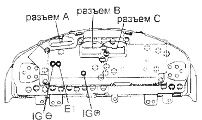
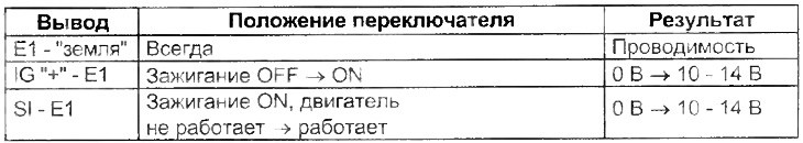
Checking the tachometer (analog-digital instrument cluster)
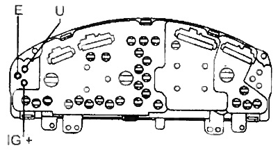
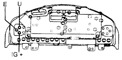
2. Check up resistance between conclusions of the index of the gauge. Resistance between pins:
- IG "+" - U - ~ 54 Ohm
- IG "+"-E - ~ 176 Ohm
- UE - ~230 Ohm
analog
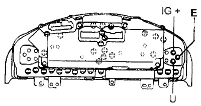
analog-digital
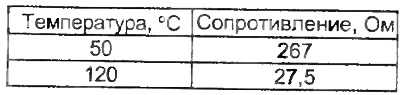
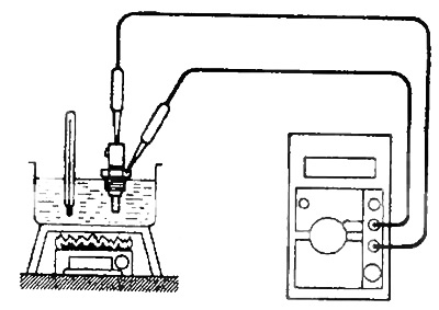
Checking the coolant temperature sensor
Check the resistance between the sensor lead and the housing at various temperatures.
 |  |
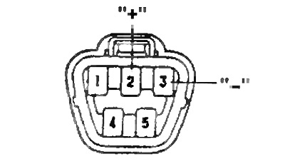
Checking the fuel gauge
1. Measurements at work.
A) Remove the rear seat cushion and disconnect the sensor connector.
b) Turn the ignition on and make sure the arrow is in position "E".
V) From the position specified in paragraph (b), short the leads "2" And "3" connector on the wiring harness side. Make sure the arrow is in position "F".
Note: when the jumper is removed, the pointer will drop to the position "E" after 4 minutes.
2. Resistance check.
analog
Resistance between pins:
- IG "+" - U - ~ 108 Ohm
- IG "+" - E - ~ 233 Ohm
- U-E - ~ 125 Ohm
analog-digital
Resistance between pins:
- IG "+" - U - ~ 107 Ohm
- IG "+" - E - ~ 256 Ohm
- U-E - ~ 150 Ohm
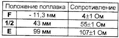
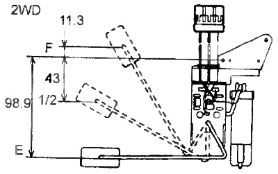
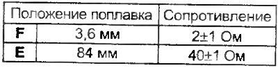
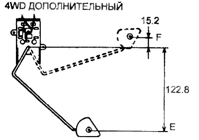
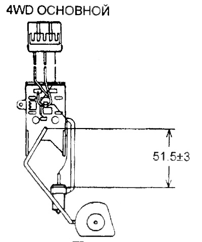
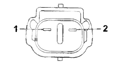
Checking the fuel level sensor
1. Resistance check.
A) Remove the fuel level sensor and check that the float moves smoothly.
b) Measure resistance between leads "2" And "1" when moving the float from the position "E" V "F". Make sure the resistance changes smoothly.
2WD
 |  |
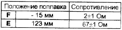
4WD (basic)
 | 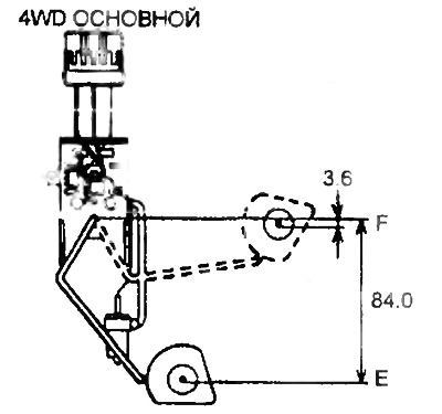 |
4WD (additional)
 |  |
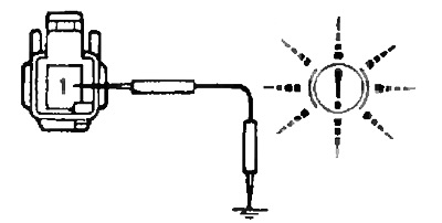
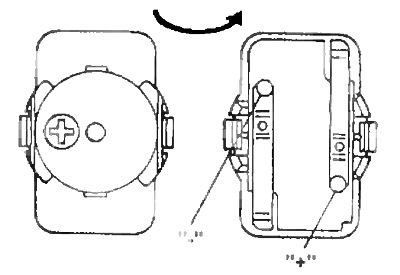
Checking the fuel reserve sensor
1. Sensor check.
A) Remove the fuel level sensor.
b) Turn on the ignition and make sure that when the sensor is lowered into gasoline, the indicator does not light up.
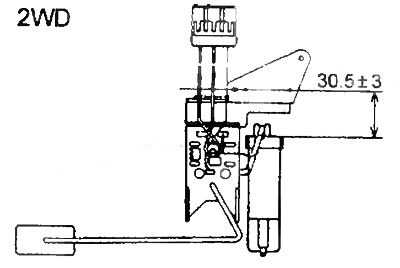
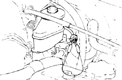
2. Checking the installation height of the sensor (according to the picture).
Checking the indicator and sensor for the presence of water in the fuel filter
1. Checking the operation of the indicator.
A) Disconnect the connector from the indicator switch and connect the connector pins on the indicator side.
b) Turn on the ignition and check» that the indicator lamp lights up and the buzzer sounds.
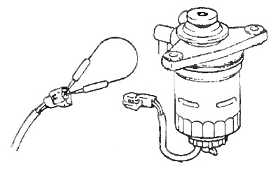
2. Checking the sensor for the presence of water in the fuel filter.
A) Remove the fuel filter water sensor.
b) Check for continuity between the terminals of the connector when the switch is in the "OFF" (float lowered).
V) Check for continuity between the terminals of the connector in the switch position "ON" (float in top position).
Resistance between pins:
- Float in the upper position - 7.3 - 9.5 ohms
- Float in lower position - no conductivity
Checking the daily run switch
1. Conductivity test.
A) Remove the switch.
b) Check the continuity between the terminals of the connector on the switch side.
- Trip switch in position "ON" - conductivity between terminals "2" And "3".
- Trip reset switch in position "ON" - conductivity between terminals "1 "And "2".
Checking the rheostat
1. Conductivity test.
A) Remove the rheostat.
b) Measure the resistance between the leads.
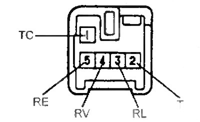
Lamp Fault Indicator Sensor Test
Resistance:
- RL-RE - 10 kOhm
RV-RE
- minimum - 0 ohm
- maximum - 10 kOhm
TS-T
- neutral position - no conduction
- the rest are conductivities
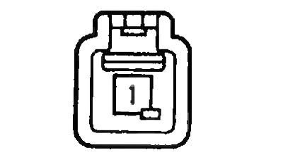
Seat Belt Sensor Test
Disconnect the connector and check the continuity between the terminals "1" And "3" sensor connector.
- The belt is not fastened - there is conductivity
- fastened - no conduction
Checking the emergency oil pressure sensor
1. Check for continuity between terminal and "earth" when the engine is not running.
2. Check for continuity between terminal and "earth" poi running engine.
Lamp Fault Indicator Sensor Test
Check according to the table.
Checking the brake system indicator
1. Checking the circuit.
A) Disconnect the parking brake sensor connector.
b) Turn on the ignition.
V) Ground the terminal of the connector on the side of the parking brake sensor harness and check that the indicator light is on.
G) Disconnect the low brake fluid sensor connector.
d) Turn on the ignition.
e) Short-circuit the connector leads on the harness side of the low brake fluid level sensor and verify that the light is on.
Checking the parking brake sensor
Check for continuity between the sensor connector pin and "earth".
- The stem is pressed - no conductivity
- The stem is not pressed - there is conductivity
Checking the Low Brake Fluid Sensor
1. Disconnect the low brake fluid level sensor connector and connect a tester.
2. Pump out the brake fluid with a syringe and at this time check the conductivity.
- Float on top - no conductivity
- Float at the bottom - there is conductivity
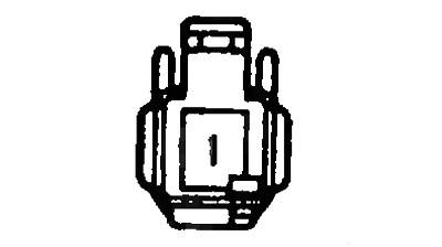
Limit switch check
Check for continuity between pin 1 of each connector and "earth".
- Switch pressed - no conduction
- not pressed - there is conductivity
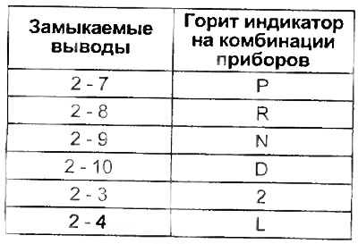
Checking the automatic transmission selector position indicator
Note: the test is carried out with the ignition key in the ON position and the automatic transmission selector in the position "R".
1. Disconnect the automatic transmission selector connector.
2. Turn on the ignition, short the leads on the wiring harness side and check that the corresponding indicator on the instrument cluster is on.
Note: check that when switching the automatic transmission selector to the position "R" the corresponding indicator on the instrument cluster lights up and a buzzer sounds.
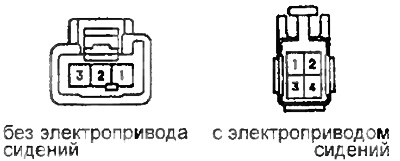
Checking the indicator and buzzer when reversing
1. Check that when switching the automatic transmission selector in position "R" the corresponding indicator on the instrument cluster lights up and a buzzer sounds.
2. Remove the buzzer and connect "+" battery to the positive terminal of the buzzer, but to the negative terminal and make sure that the buzzer sounds.
Checking the overdrive indicator
1. Check up conductivity between conclusions 2 and 4 sockets of the switch at various provisions of the last.
- OD ON - no conduction
- OD OFF - no conduction
Checking the automatic transmission mode indicator
1. Check up conductivity between conclusions of a socket of the switch at various provisions of the last.
 | 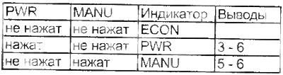 |