
Examination
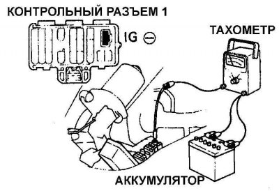
Connecting the tachometer to the IG terminal of the data link connector located in the lower part of the engine compartment
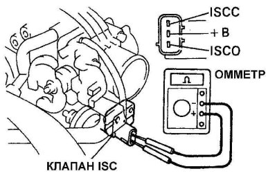
Checking resistance between +BI and SCC and +BI and SCO air control valve electrical connector pins on a four-cylinder engine
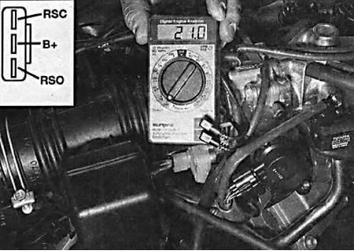
Checking the resistance between the contacts of the electrical connector of the air control valve + BI and RSC and + B and RSO on the 1MZ-FE V6 engine
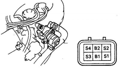
Checking resistance between air control valve electrical connector pins B1 and S1 and B1 and S3, and between pins B2 and S2 and pins B2 and S4
1. Apply the handbrake and place the shift lever in neutral. Connect a tachometer in accordance with the manufacturer's instructions. Connect the wire from the tachometer to the IG terminal of the electrical connector (see fig. Connecting the tachometer to the IG terminal of the data link connector located in the lower part of the engine compartment). Start the engine, warm it up to normal operating temperature and measure the idle speed.
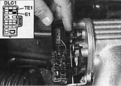
2. Using an additional wire, close contacts TE1 and E1 of the electrical connector.
3. When contacts TE1 and E1 are closed, the engine speed should increase to 1000–2000 rpm within 5 seconds. Then the idle speed should be set.
4. Remove the extra ground wire.
5. Disconnect the electrical connector from the IAC air control valve.
6. Measure the resistance between the middle pin and the side pins of the electrical connector (see fig. Check of resistance between contacts of an electric socket of the control air valve +BI and SCC and +BI and SCO on the four-cylinder engine, fig. Check of resistance between contacts of an electric socket of the control air valve + BI and RSC and + B and RSO on the 1MZ-FE V6 engine, fig. Checking resistance between air control valve electrical connector pins B1 and S1 and B1 and S3, and between pins B2 and S2 and pins B2 and S4).
7. Connect the electrical connector to the air control valve.
Replacement
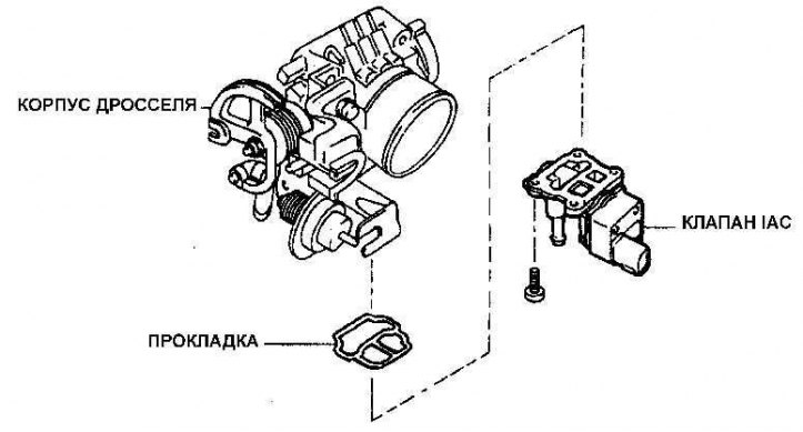
Elements of fastening of the control air valve
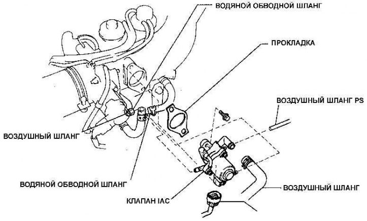
Elements of fastening of the control air valve on the engine 3VZ-FE V6
1. Remove the throttle body.
2. Unscrew the screws and remove the control air valve together with the gasket (see fig. Elements of fastening of the control air valve and fig. pic. Elements of fastening of the control air valve on the engine 3VZ-FE V6).
3. Installation of the control air valve is made in sequence, return to removal.