
Examination
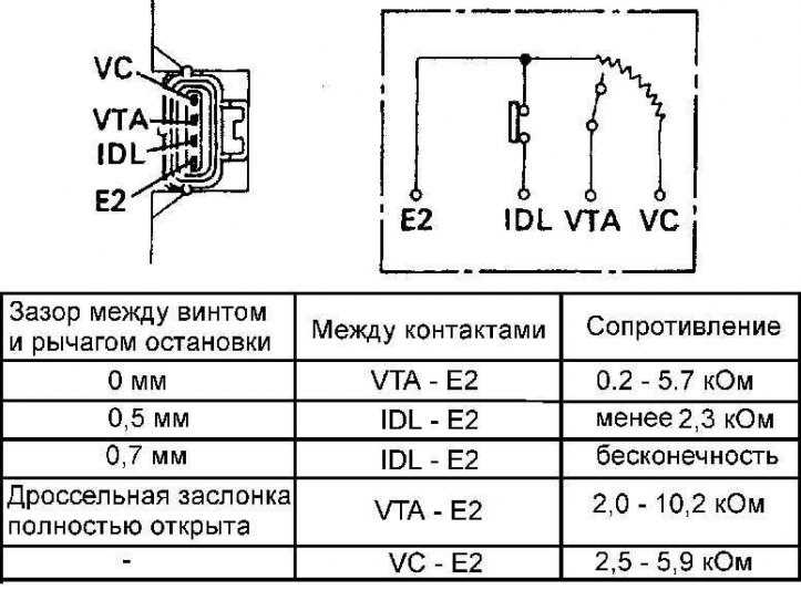
Checking the resistance between the corresponding terminals of the throttle position sensor on four-cylinder engines
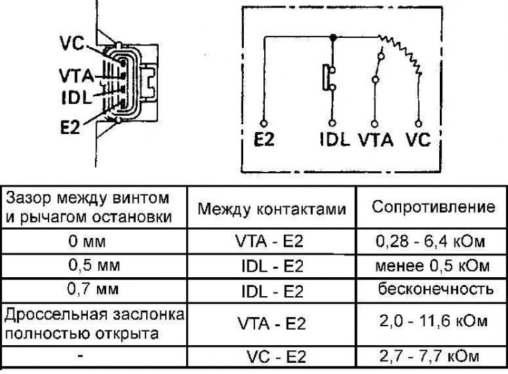
Checking the resistance between the corresponding pins of the throttle position sensor connector on six-cylinder engines
1. Disconnect the electrical connector from the throttle position sensor (TPS) and apply vacuum to the throttle positioner.
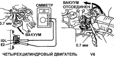
2. Install a 0.7 mm feeler gauge between the idle speed screw and stop.
3. Using an ohmmeter, measure the resistance between the corresponding pairs of electrical connector pins (see fig. Resistance check between corresponding contacts of the gauge of provision of a throttle shutter on four-cylinder engines and fig. Checking the resistance between the corresponding pins of the throttle position sensor connector on six-cylinder engines).
If the measured resistance differs from the required values, install a 0.7 mm thick probe between the idle speed adjustment screw and stop and connect an ohmmeter to the IGL and E2 contacts. Loosen the throttle position sensor mounting screws and slowly rotate the sensor clockwise until the ohmmeter reads infinity.
4. Tighten the throttle position sensor mounting screws, install the probe and re-measure the resistance between the corresponding pins.
Replacement
If the sensor adjustment does not bring positive results, unscrew the screws securing the sensor and replace the sensor with a new one.