
2. Secure the drive shaft in a soft jaw vise.
Disassembly
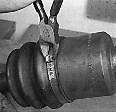
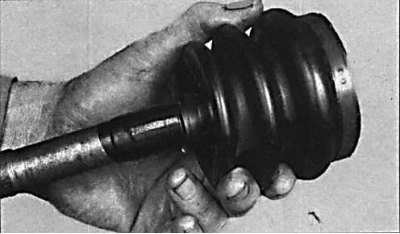
1. Remove the clamps securing the protective cover of the constant velocity joint.
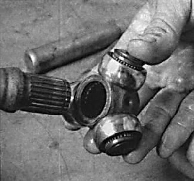
2. Slide the protective rubber boot onto the drive shaft and remove the three-arm joint from the joint housing.
3. Mark the mutual position of the three-arm joint and the drive shaft for the correct re-installation of the joint on the shaft.
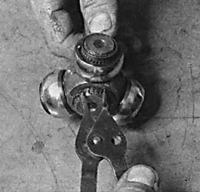
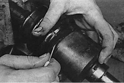
4. Remove the circlip securing the three-arm joint to the drive shaft.
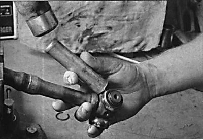
5. Using a hammer and a copper drift, knock the three-arm joint off the drive shaft.
6. Remove the protective cover from the drive shaft.
Examination
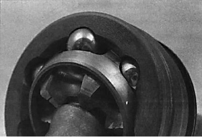
1. Remove old grease from inner and outer CV joints. Using an appropriate solvent, clean the hinges of grease residues. Check the condition of the CV joints for wear and pitting.
Assembly
Drive shafts on models with 5S-FE engines
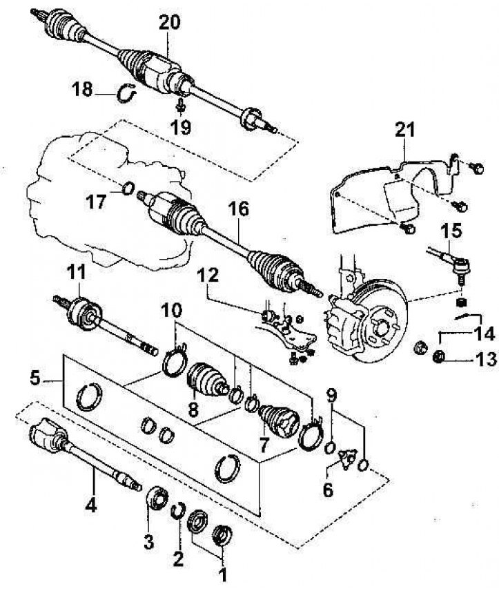
1 - dust cap; 2 - compression ring; 3 - bearing; 4 - intermediate shaft; 5 – collars of fastening of protective covers; 6 - three-arm hinge; 7 - protective cover; 8 - protective cover; 9 - retaining ring; 10 – collars of fastening of protective covers; 11 - drive shaft; 12 – thrust of the anti-roll bar; 13 - locknut; 14 - cotter pin; 15 – a tip of steering draft; 16 - left drive shaft; 17 - retaining ring; 18 - retaining ring; 19 – a bolt of fastening of the intermediate bearing; 20 - right drive shaft; 21 - protection of the front wing
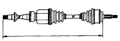
Measuring Drive Shaft Length on Models with 5S-FE Engines
1. Wrap the spline of the drive shaft with adhesive tape and install the protective covers of the constant velocity joints on the drive shaft.
 |  |
2. Remove the adhesive tape from the splines of the drive shaft and install the three-arm joint on the drive shaft and secure it with a circlip.
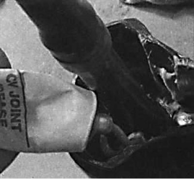
3. Lubricate the CV joint housing and lubricate the three-arm joint.
4. Install the three-arm joint with the drive shaft into the joint housing.
5. Install the new protective boot on the drive shaft so that the flange of the protective boot fits into the grooves of the drive shaft.
6. By moving the three-arm joint in the joint housing, set the required length of the drive shaft (see fig. Measuring Drive Shaft Length on Models with 5S-FE Engines).
7. Using a screwdriver, purge the air from under the protective cover.
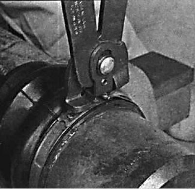
8. Secure the cover with a tie.