
Disassembly
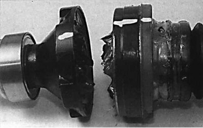
Drive shafts for models with 3VZ-FE or 1MZ-FE engines
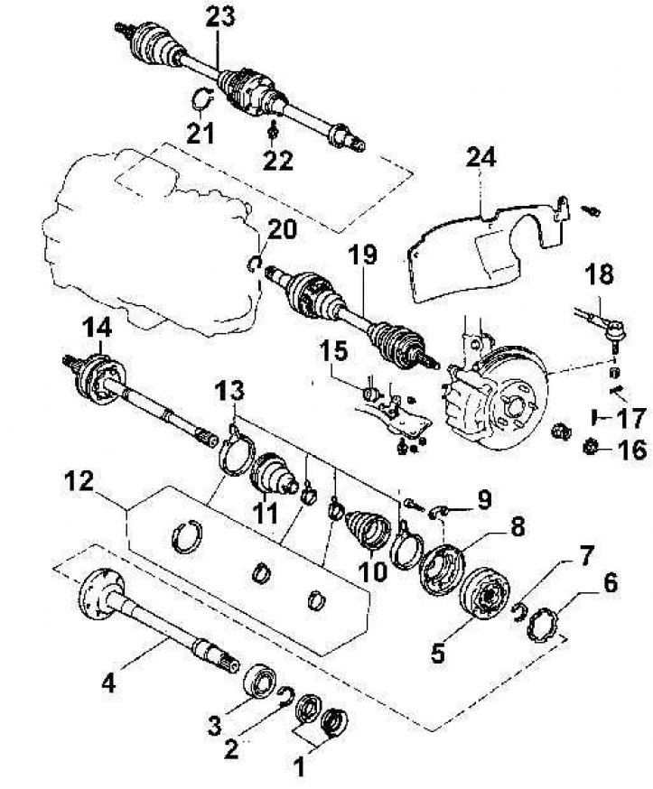
1 - dust cap; 2 - thrust ring; 3 - bearing; 4 - intermediate shaft; 5 - hinge of equal angular velocities; 6 - gasket; 7 - retaining ring; 8 - hinge casing; 9 - plate; 10 - protective cover; 11 - protective cover; 12 - clamps for fastening protective covers of the GKN type; 13 - clamps for fastening protective covers of the TOYOTA type; 14 - external hinge of equal angular velocities; 15 – thrust stabilizer; 16 - locknut; 17 - cotter pin; 18 – a tip of steering draft; 19 - left drive shaft; 20 - retaining ring; 21 - retaining ring; 22 – a bolt of fastening of the intermediate bearing; 23 - right drive shaft; 24 - protection of the front wing
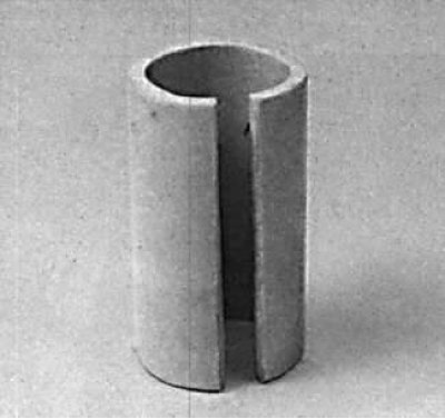
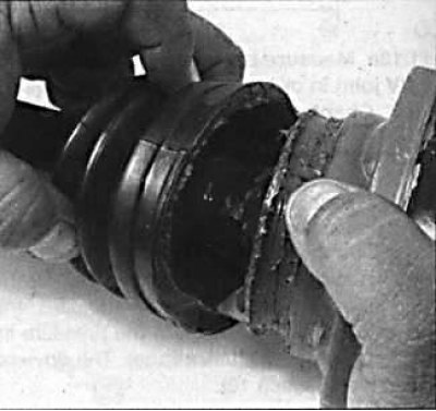
Cut rubber hose used to remove CV joint
1. Remove the clamps securing the protective cover.
 |  |
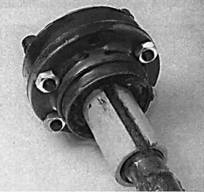
2. Unscrew 6 bolts of fastening of the internal hinge of a power shaft.
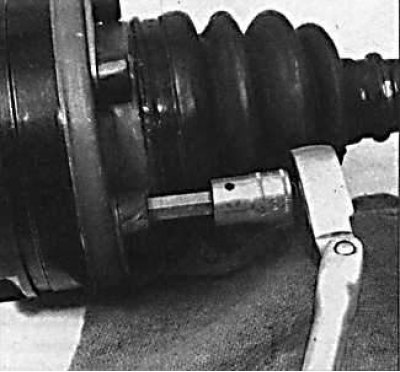
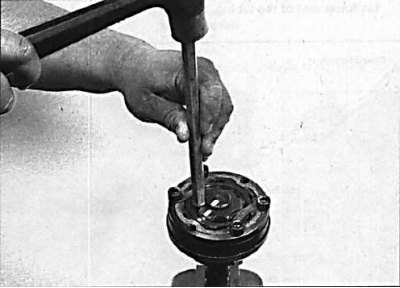
3. Using a copper drift, knock the drive flange off the driveshaft inner pivot.
4. Separate the drive flange from the drive shaft pivot.
 | 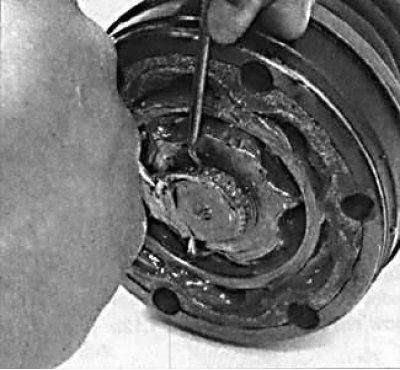 |
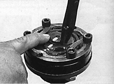
5. Using pliers or a screwdriver, remove the retaining ring securing the constant velocity joint to the drive shaft.
 |  |
6. Slide the protective cover of the constant velocity joint onto the drive shaft.
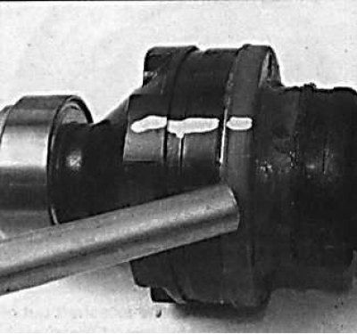
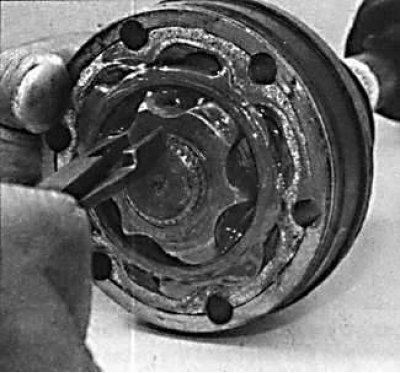
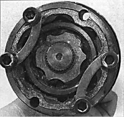
7. Using two curved plates and 4 bolts, secure the internal elements of the hinge from falling out of the housing.
8. Install the cut piece of hose 75 mm long (see fig. Cut rubber hose used to remove CV joint) on the drive shaft to the ball joint.
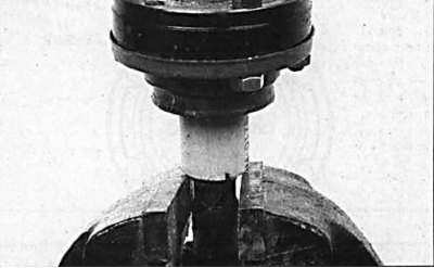
9. Place the drive shaft with the joint in a vise so that the rubber hose rests on the jaws of the vise.
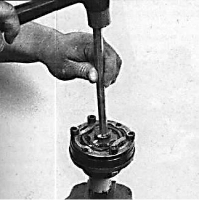
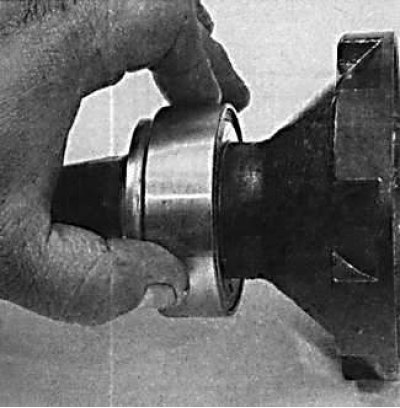
10. Mark the relative position of the inner ring of the housing and the outer ring of the hinge and, using a copper drift, knock out the drive shaft from the hinge.
Examination
1. Clean the old grease from the constant velocity joint. Using a solvent, clean the hinge from traces of old grease. Check hinge parts for wear and pitting.
2. Check that the intermediate bearing rotates easily and without binding.
Assembly
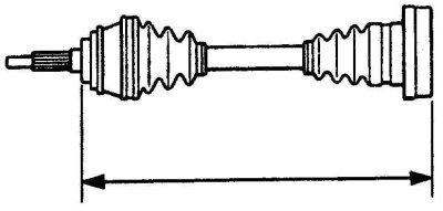
Drive shaft length measurement
1. Install new CV joint boots on the drive shaft.
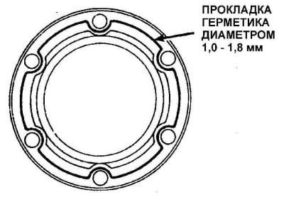
2. Apply a thin layer of sealant to the mating surface of the pivot housing.
3. Install the cover on the inner hinge. At the same time, align the holes for the mounting bolts in the casing and the inner hinge. Temporarily install bolts in the holes.
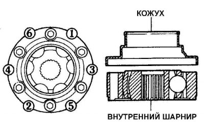
4. Using a plastic mallet and striking in the sequence shown in the illustration, push the cover onto the inner hinge.
5. Install the inner joint on the drive shaft in accordance with the previously made marks.
6. Secure it with a retaining ring.
7. Fill the joint with grease.
8. Screw the drive flange or intermediate shaft to the inner joint.
9. Install the protective cover on the constant velocity joint.
10. Set the required length of the drive shaft, then, using a screwdriver, remove air from under the protective boot and secure the protective boots with clamps (see fig. Drive shaft length measurement).