
Note: Installation is in reverse order of removal. After installation, check the operation of the speed sensors (ABS) and the angle of the front wheels.
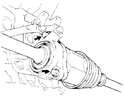
Caution: The wheel bearing can be damaged if it is subjected to the weight of the vehicle, such as when the vehicle is moved with the drive shaft removed. Therefore, if it is necessary to move the vehicle with the drive shaft removed, first fix the hub bearing as shown in the figure.
1. Jack up the car, remove the front wheel and protective apron.
- Tightening torque - 105 Nm
2. Loosen the locknut.
A) Remove cotter pin and locknut cap.
b) Loosen the locknut with the brake pedal depressed.
- Tightening torque - 220 Nm
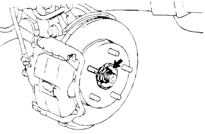
3. Turn away a bolt and remove the sensor of frequency of rotation (ABS).
- Tightening torque - 8 Nm
4. (Manual transmission)
Drain the gear oil. (Automatic transmission)
Drain the working fluid.
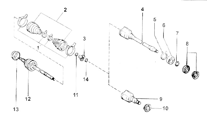
Removing the front drive shaft.
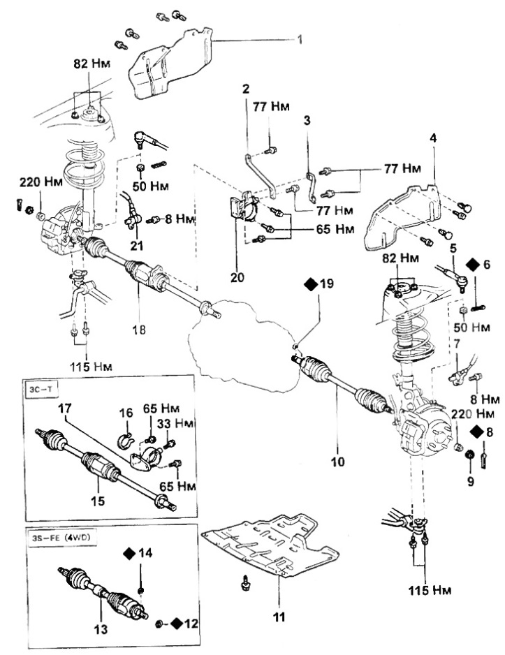
1, 4 - protective apron,
2 - bracket stand,
3 - bracket stand,
5 - tie rod end,
6, 8 - cotter pin,
7, 21 - speed sensor (ABS),
9 - locknut cap,
10 - drive shaft (left),
11 - engine protection cover (with manual transmission),
12 - ring seal,
13, 15, 18 - drive shaft (right),
14, 19 - retaining ring,
16 - retaining ring,
17, 20 - bearing bracket.
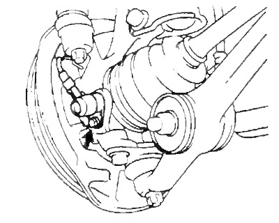
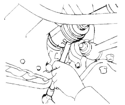
5. Disconnect the tie rod end from the steering knuckle.
- Tightening torque - 50 Nm
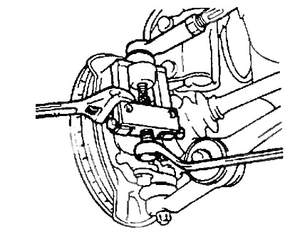
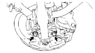
6. Turn away two bolts and disconnect the bottom spherical support from a rotary fist.
- Tightening torque - 115 Nm
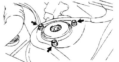
7. Turn away three nuts from the top party of a rack.
- Tightening torque - 82 Nm
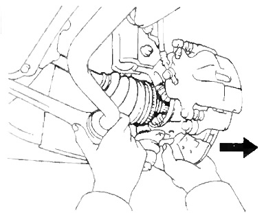
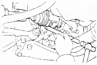
8. Disconnect the drive shaft.
A) Using a plastic mallet, remove the drive shaft from the hub.
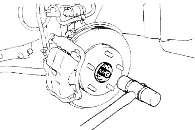
Note: Be careful not to damage the hinge cover.
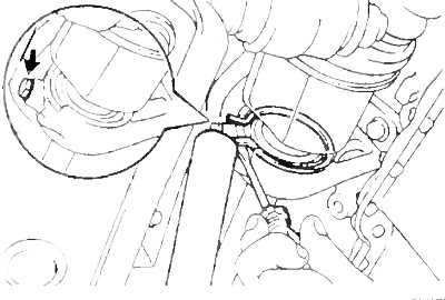
b) Pull the hub towards you by depressing the lower lever as shown in the figure and remove the drive shaft.
9. Disconnect the left drive shaft as shown.
manual transmission
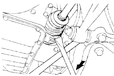
automatic transmission
Installation note:
- Apply gear oil to the intermediate shaft splines.
- turn the circlip on the drive shaft with the slit down.
- After installing the drive shaft, make sure there is an axial clearance of 2-3mm.
- After installation, make sure that the drive shaft cannot be removed by hand.
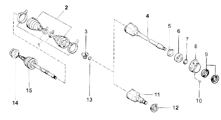
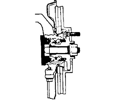
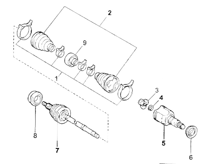
Drive shaft (4S-FE, 3S-FE (2WD)).
1 - collar,
2 - cover,
3 - triple hinge,
4 - an intermediate shaft with an internal hinge cage (right shaft),
5 - retaining ring,
6 - bearing,
7 - retaining ring,
8 - bearing holder,
9 - anther,
10 - pin,
11 - holder of the inner hinge (left shaft),
12 - anther,
13 - retaining ring,
14 - anther No. 2,
15 - shaft with external hinge assembly.
Drive shaft (ZS-T).
1 - clamp,
2 - cover,
3 - triple hinge,
4 - clip of the internal hinge (right shaft),
5 - retaining ring,
6 - bearing,
7 - retaining ring,
8 - anther,
9 - holder of the inner hinge (left shaft),
10 - anther,
11 - retaining ring,
12 - shaft with external hinge assembly,
13 - anther No. 2,
14 - retaining ring.
Drive shaft (3S-FE (4WD)).
1 - clamp,
2 - cover,
3 - triple hinge,
4 - retaining ring,
5 - clip of the internal hinge,
6 - anther,
7 - shaft with external hinge assembly,
8 - anther No. 2,
9 - damper.
10. Remove the right power shaft.
a) (4S-FE, 3S-FE (2WD))
Remove the two bolts securing the bearing holder to the bracket.
- Tightening torque - 65 Nm
(ZS-T)
Turn away a lock bolt and remove a lock ring and a power shaft.
- Tightening torque - 33 Nm
Installation note: Apply gear oil to the intermediate shaft splines.
b) (4WD)
Disconnect the drive shaft as shown.
V) Turn away bolts of fastening and remove an arm of the bearing.
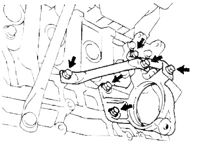
4S-FE, 3S-FE
Torque (4S-FE, 3S-FE):
- bracket bolt - 65 Nm
- bracket strut bolt - 77 Nm
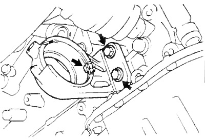
ZS-T
- Torque (ZS-T) - 65 Nm