
Removing
1. Remove the gearbox.
2. Remove the clutch cover and disc.
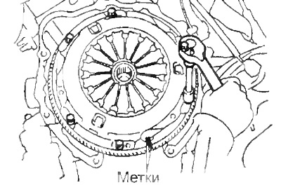
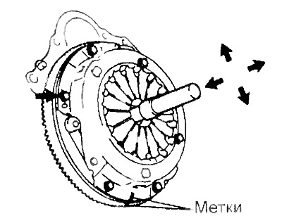
A) Mark the clutch cover and flywheel.
b) Loosen each bolt one turn in turn to ensure that the preload is evenly released from the spring.
V) Turn out all adjusting bolts and remove a casing of coupling and a coupling disk.
Attention: do not drop the clutch disc when removing.
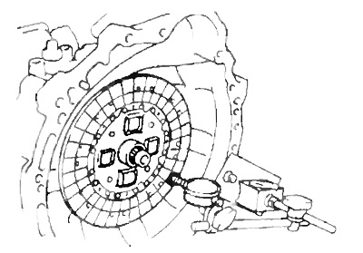
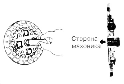
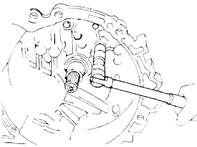
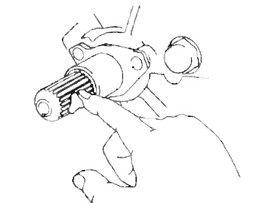
3. Remove bearing and clutch release fork.
A) Remove the bearing and clutch release fork assembly, and then remove the bearing from the fork.
b) Remove the cover.
4. If necessary, unscrew the fork support from the clutch housing.
Examination
1. Check the clutch disc for wear and damage.
Using a caliper, measure the depth of the rivet heads from the lining surface.
- Minimum depth - 0.3 mm
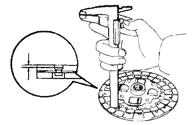
If the depth is less than acceptable, then repair or replace the clutch disc.
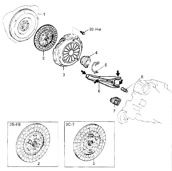
Cover and clutch disc.
1 - flywheel,
2 - clutch disc,
3 - clutch cover,
4 - clutch release bearing,
5 - spring,
6 - clutch release fork,
7 - cover,
8 - clutch release fork support.
2. Using a dial gauge, check the disc runout.
- Maximum runout - 0.8 mm
If the maximum runout exceeds the allowable value, then replace the disc.
3. Using a vernier caliper, measure the depth and width of the diaphragm spring leaf wear groove.
Maximum allowable wear:
- by depth (A) - 0.5 mm
- in width (IN) - 6.0 mm
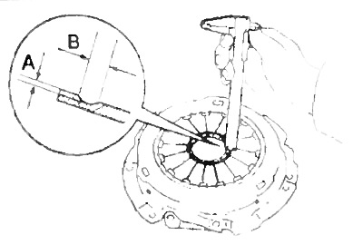
If the wear exceeds the limit, replace the clutch cover.
4. Using a dial indicator, check the flywheel runout.
- Maximum runout - 0.1 mm
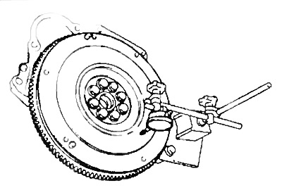
If the maximum runout exceeds the allowable value, then turn or replace the flywheel.
5. Check the clutch release bearing. By turning the bearing by hand, apply force to it in the axial direction.
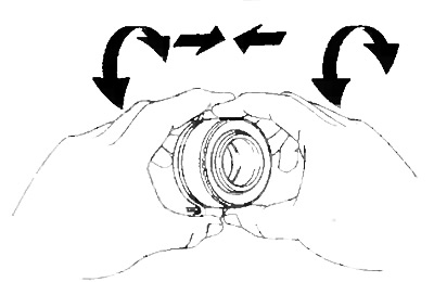
If the bearing sticks or turns with difficulty, replace the bearing.
Note: The release bearing is lubricated for life and does not require cleaning or lubrication.
Installation
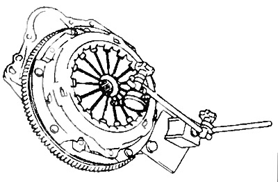
1. Install the clutch disc and clutch cover to the flywheel.
A) Using a mandrel, install the clutch disc on the flywheel.
b) Align the marks on the clutch cover and flywheel made during disassembly.
V) Temporarily tighten the bolts.
G) Do not remove the mandrel until the final tightening of the bolts.
- Tightening torque - 19 Nm
Note: Tighten the bolts evenly over several passes in a criss-cross pattern.
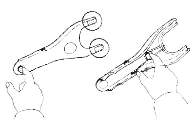
2. Check the relative position of the ends of the petals of the diaphragm spring using a special tool.
- Maximum deviation from the plane - 0.5 mm
If the deviation exceeds the allowable value, then adjust it using a special tool.
3. Install the fork support in the clutch housing (if it was removed).
A) (E59F) Clean the threads of the support with a solvent to remove any adhesive sealant residue. Apply adhesive sealant to the last three threads of the support.
b) Install and tighten the support.
Torque:
- S50, S51 - 40 Nm
- E59F - 48 Nm
4. Apply grease to the surface of the following parts:
- at the contact points of the fork and the clutch release bearing;
- at the point of contact of the clutch release fork and the rod of the working cylinder;
- at the contact point of the support and the clutch release fork.
- - on the splines of the input shaft of the gearbox.
5. Connect bearing and clutch release fork. Then install them on the gearbox.
6. Install the gearbox.