
Shift Lever Lock System (TMS system)
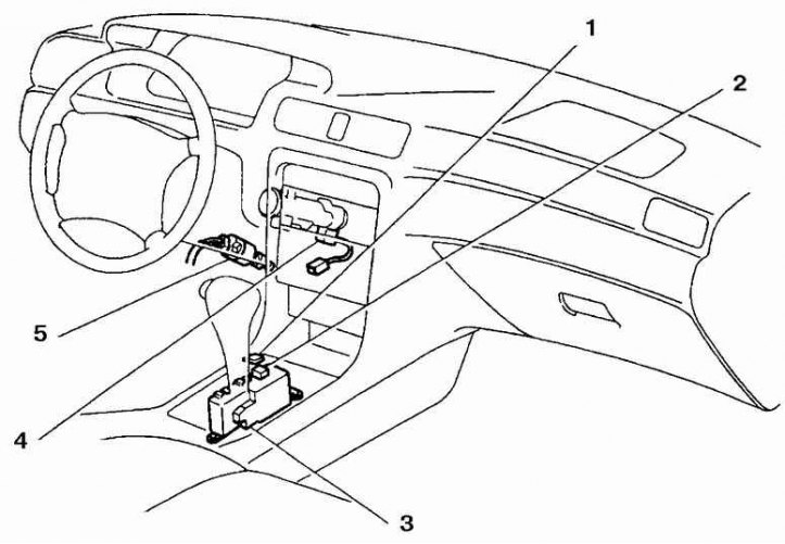
1. Lock release button cover 2. Lock release button 3. Lock electronic control unit 4. Ignition lock solenoid valve 5. Stop lamp switch
Shift Lever Lock System (TMMK system)
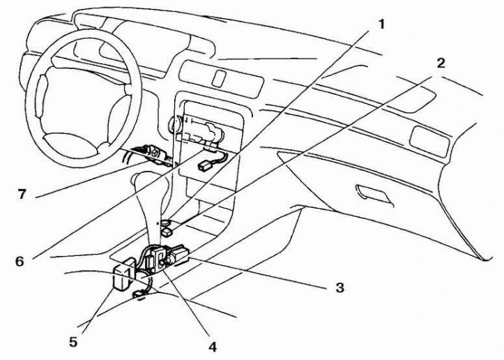
1. Cover of the button of shutdown of system of blocking; 2. Button to disable the locking system; 3. Solenoid valve to lock the shift lever; 4. Lever lock control switch; 5. Electronic control unit for the locking system; 6. Solenoid valve for blocking the ignition lock; 7. Stop lamp switch
Contacts of the electronic unit
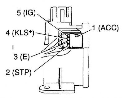
Voltage table (TMS system)
Contact number | Measurement conditions | Voltage (volt) |
1 – 3 (ACC - E) | Ignition key in ACC | 10 – 14 |
5 – 3 (IG-E) | Ignition key in ON | 10 – 14 |
2 – 3 (STP-E) | Brake pedal depressed | 10 – 14 |
4 – 3 (RLS ± E) | (1) Ignition key in ACC and shift lever in park position | 0 |
| (2) Ignition key in ACC, shift lever in any position except park | 7,5 – 11 | |
| (3) Ignition key in ACC, shift lever in any position except park (approximately 1 sec.) | 6 – 9,5 |
Contacts of the electronic unit
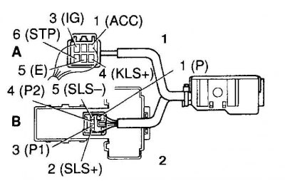
1. Back side
2. Front side
Voltage table (TMMK system)
Contact number | Measurement conditions | Voltage (volt) |
| A,1 - A,5 (ACC–E) | Ignition key in ACC position | 10 – 14 |
| A,3 - A,5 (IG–E) | Ignition key in the ON position | 10 – 14 |
| A.6 – A.5 (STP–E) | Brake pedal depressed | 10 – 14 |
| A.4 – A.5 (KLS ± E) | (1) Ignition key in ACC and shift lever in park position | 0 |
| (2) Ignition key in ACC, shift lever in any position except park | 7,5 – 11 | |
| (3) Ignition key in ACC, shift lever in any position except park (approximately 1 sec.) | 6 – 9,5 | |
| B.2 – B.5 (SLS ± SLS –) | (1) Ignition key in ON, shift lever in park position | 0 |
| (2) Brake pedal depressed | 8 – 13,5 | |
| (3) Shift lever in any position except park | 0 | |
| B.3 – B.1 (P1 – P) | (1) Ignition key ON, lever in park position and brake pedal depressed | 0 |
| (2) Ignition key ON, lever in any position except park, brake pedal depressed | 9 – 13,5 | |
| B.4 – B.1 (P2 – P) | (1) Ignition key in ACC and shift lever in park position | 9 – 13,5 |
| (2) Ignition key in ACC, shift lever in any position except park | 0 |
The shift lever lock system prevents the shift lever from being moved from park to any other position unless the brake pedal is depressed. The system consists of a stop lamp switch, an ignition lock solenoid valve, an automatic lock system release button, a shift lever lock solenoid valve, a lock system control switch, and an electronic lock system control unit.
Examination
Electronic control unit
1. Remove the shift lever panel. The control unit for the locking system is located behind the lever or on the side of the gear lever.
2. Using a voltmeter, measure the voltage between the indicated contacts of the electronic unit, observing the necessary conditions. See voltage table (TMS system) and Table of stresses system TMMK).
3. If the readings obtained do not meet the requirements, replace the electronic unit.
Solenoid valve for gear lever lock system (TMMK)
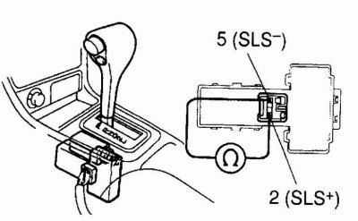
1. Disconnect the solenoid valve wire and connect an ohmmeter to the solenoid valve contacts. Compare your result with the specifications.
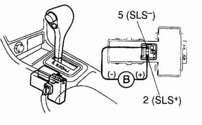
2. Apply battery voltage to the indicated solenoid valve contacts. You should hear a click.
3. Replace the solenoid valve if necessary.
Ignition lock solenoid valve (tms and tmmk)
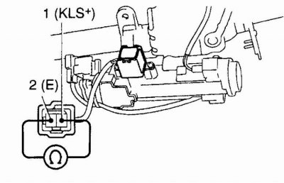
1. Disconnect the solenoid valve wire and connect an ohmmeter to the solenoid valve contacts. Compare your result with the specifications.
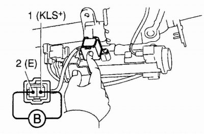
2. Apply battery voltage to the indicated solenoid valve contacts. You should hear a click.
3. Replace the solenoid valve if necessary.