
Removing
1. (For vehicles equipped with an airbag)
Remove the steering wheel pad (see chapter "Safety system (SRS)").
Attention: store the steering wheel pad face up.
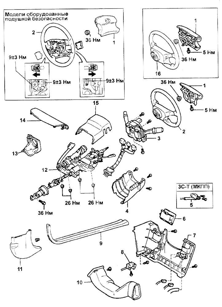
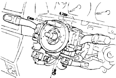
Removing the steering column.
1 - steering wheel pad,
2 - steering wheel,
3 - combined switch,
4 - the lower casing of the steering column,
5 - idle speed adjustment lever when the diesel engine is warming up,
6 - additional glove box,
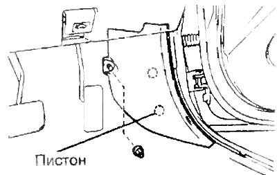
7 - lower trim panel on the driver's side,
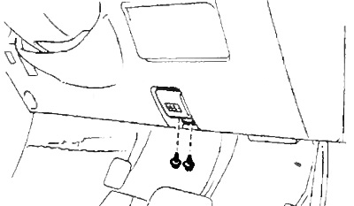
8 - hood lock lever,
9 - front door sill trim,
10 - air duct,
11 - side trim,
12 - steering column assembly,
13 - casing of the ignition switch,
14 - lower trim of the instrument cluster,
15 - the upper casing of the steering column.
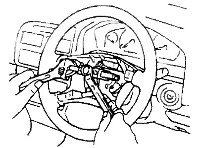
2. Remove the steering wheel.
A) Loosen the nut. Mark the main shaft and steering wheel.
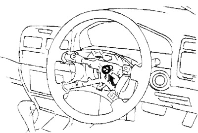
- Tightening torque - 36 Nm
b) Using the special tool, remove the steering wheel.
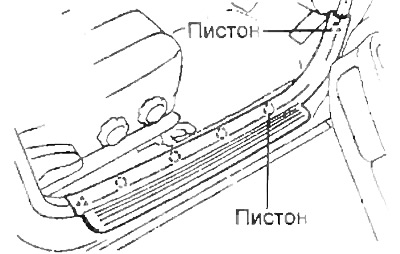
3. Remove finishing of a threshold of a forward door.
4. Remove the side trim.
5. (ZS-T with manual transmission)
Loosen the mounting screws and disconnect the idle speed control lever when the diesel engine is warming up.
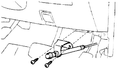
6. Remove the hood lock lever.
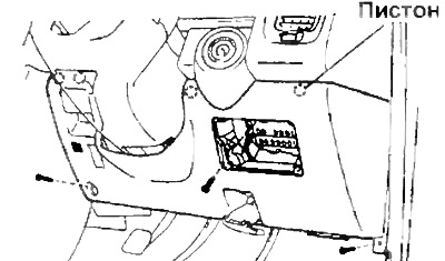
7. Remove the bottom finishing panel from the driver's side.
8. Remove the air duct.
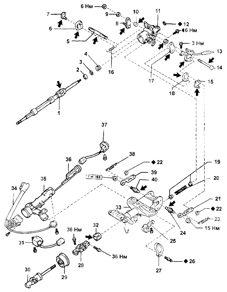
Steering column.
1 - main shaft,
2 - bearing,
3 - thrust ring,
4 - spring,
5 - axis of levers,
6, 18 - auxiliary lever for adjusting the angle of inclination,
7, 15 - dog retainer,
8, 17 - doggy,
9 - spacer,
10 - bushing,
11 - the upper tube of the steering column,
12 - retaining ring,
13 - lever for adjusting the angle of inclination,
14 - bolt-axle,
16 - spring,
17 - a bolt with a conical head,
19 - spring seat,
20 - compression spring,
21, 39 - tilt angle adjustment lever holder,
22 - retaining ring,
23, 38 - extension spring,
24, 40 - steering column bolt,
25 - collar,
26 - a bolt with a conical head,
27 - bracket clamp,
28 - universal joint,
29 - anther,
30 - intermediate shaft with universal joint,
31 - ignition key lock solenoid valve,
32 - bushing of the main shaft,
33 - lower tube of the steering column,
34 - contact group of the ignition lock,
35 - ignition lock bracket,
36 - ignition lock cylinder,
37 - illumination of the ignition switch.
Note: when assembling, on the parts marked in the figure, apply:
- left arrow - grease
- semicircle - adhesive sealant for fixing threaded connections.
9. Remove the lower furnish of a combination of devices.
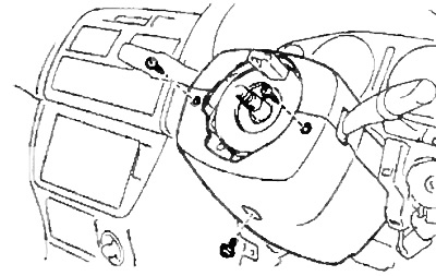
10. Turn away screws of fastening and remove casings of a steering column.
11. Turn away screws of fastening and remove the combined switch.
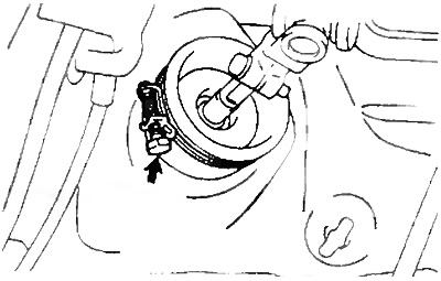
12. Disconnect the ignition lock connector. Loosen the clamp.
- Tightening torque - 36 Nm
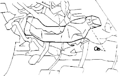
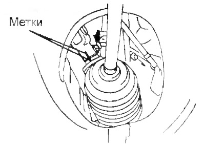
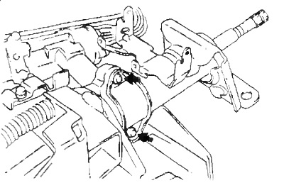
13. Apply alignment marks as shown in the figure and unscrew the bolt securing the intermediate shaft to the universal joint.
- Tightening torque - 36 Nm
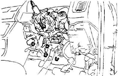
14. Turn away nuts of fastening and remove a steering column in gathering.
- Tightening torque - 26 Nm
Removing the ignition switch
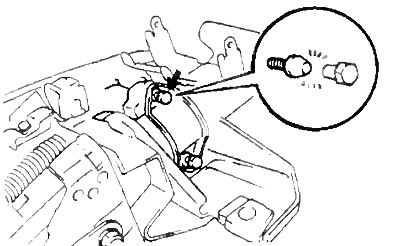
1. Drill out the conical bolts and remove them from the bracket.
2. Remove the ignition lock bracket from the steering column tube.
When connecting the ignition lock, use new bolts with a conical head. Tighten them until the heads are cut off.
Checking the ignition lock
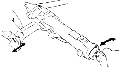
1. Check the ignition lock bracket.
Check that the steering wheel lock mechanism is working properly.
2. If necessary, replace the ignition lock cylinder.
A) Set the ignition key to position "ACC". Press the locking pin with a thin rod or screwdriver and remove the lock cylinder.
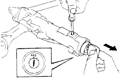
b) Set the ignition key to position "ACC" and install the new ignition lock cylinder into the bracket. Make sure the lock pin is in place.
G) Check that the steering wheel lock mechanism is working properly.
Steering column installation
Installation is carried out in the reverse order of removal. When installing, align the marks made when removing.