
Removing
When removing and installing the steering mechanism, follow the assembly drawing.
1. Remove the front wheel.
2. Drain the power steering fluid.
3. Install the engine support.
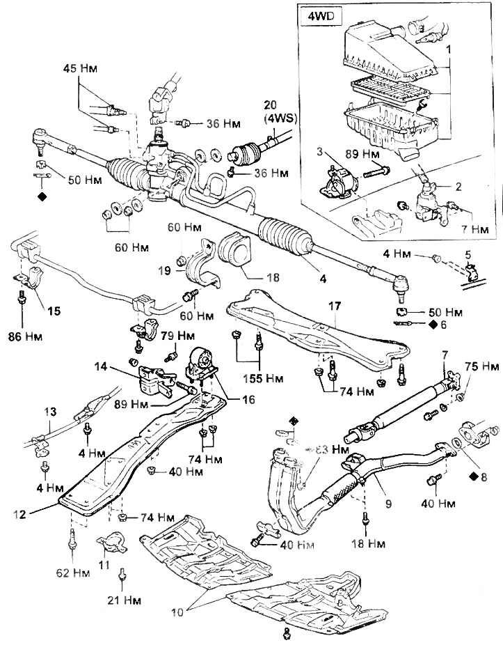
Removing the front steering gear
1 - air filter,
2 - container with activated carbon,
3, 16 - engine support,
4 - steering mechanism,
5 - collar (4WD with automatic transmission),
6 - cotter pin,
7 - front propeller shaft,
8 - gasket,
9 - exhaust pipe muffler,
10 - engine protection cover,
11 - holder,
12 - longitudinal beam,
13 - control cable (with automatic transmission),
14 - support bracket,
15 - sleeve holder,
17 - cross beam,
18 - bushing,
19 - bracket,
20 - front cardan shaft of the steering mechanism (4WS).
4. (Models with 4WS)
Lock the neutral position of the rear steering mechanism.
5. (Models with 4WS)
Remove the rear steering driveshaft.
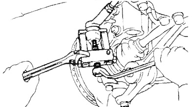
6. Disconnect the tie rod ends
A) Remove cotter pins and unscrew nuts.
b) Using the special tool, disconnect the tie rod ends from the steering knuckle.
7. Remove the motor protection cover.
8. (With automatic transmission)
Turn away bolts and disconnect collars of a cable of management of a transmission.
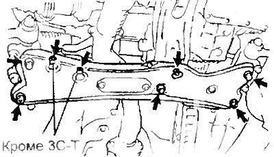
9. Turn away bolts and nuts and remove a cross beam.
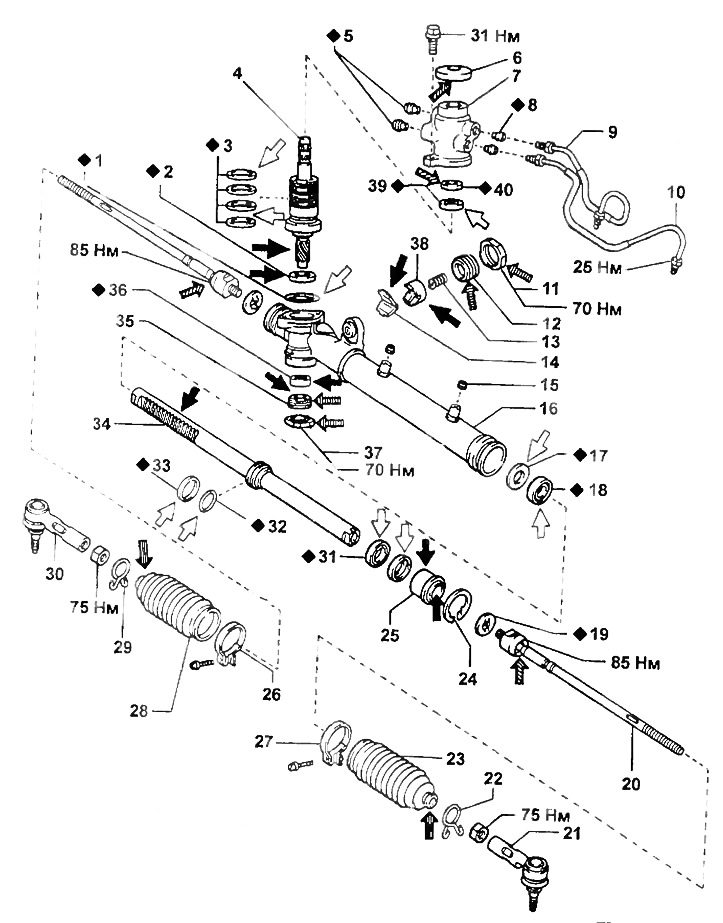
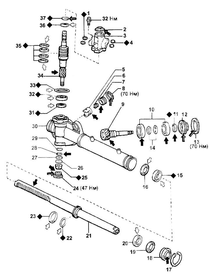
Steering gear (2WS).
1 - ring seal,
2 - stuffing box,
3 - teflon ring,
4 - a worm with a control valve,
5, 8 - fitting seat,
6 - anther,
7 - worm body with control valve,
9 - discharge pipeline,
10 - return pipeline,
11 - locknut,
12 - guide rail cover,
13 - spring,
14 - guide rail saddle,
15 - seal,
16 - steering gear housing,
17 - spacer,
18 - stuffing box,
19 - lock washer,
20 - steering rod,
21, 30 - tie rod end,
22, 29 - collar,
23, 28 - cover,
24 - retaining ring,
25 - restrictive sleeve,
26, 27 - collar,
31 - stuffing box,
32 - ring seal,
33 - teflon ring,
34 - rail,
35 - bearing guide nut,
36 - bearing,
37 - locknut,
38 - rail guide,
39 - bearing,
40 - stuffing box.
Note: when assembling, apply to the parts indicated by the arrows:
,
- grease,
- power steering fluid,
- silicone grease,
- sealant.
10. Turn away bolts of fastening and holders and plugs of the stabilizer.
11. Turn away bolts of fastening and remove the holder.
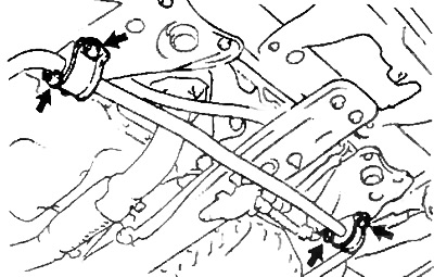
12. Turn away bolts and nuts and remove a longitudinal beam.
13. Turn away bolts and a nut and remove an engine support.
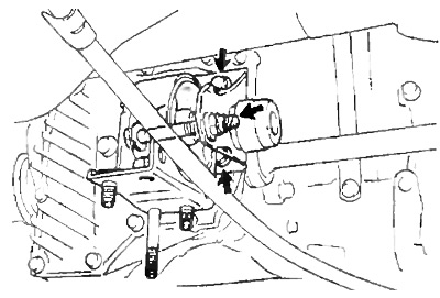
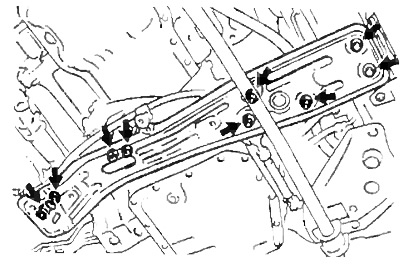
14. Disconnect the return and pressure pipes.
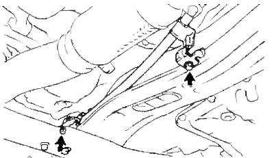
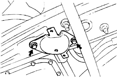
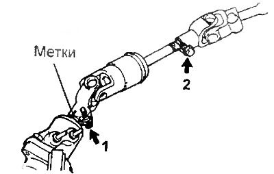
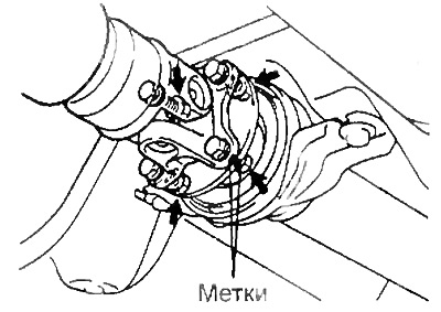
15. Disconnect the intermediate shaft.
A) Loosen the bolt (2) attaching the universal joint to the intermediate shaft.
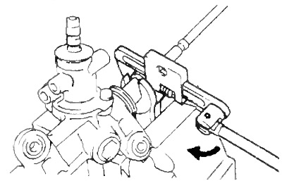
b) Apply alignment marks, unscrew the bolt (1) and disconnect the intermediate shaft with the universal joint from the worm.
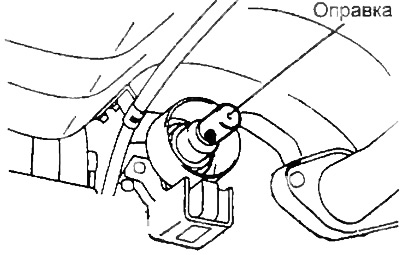
16. (4WD)
A) Remove the air filter.
b) Remove the activated charcoal container assembly with the bracket.
V) Remove the left engine mount.
G) Apply alignment marks and disconnect the front propeller shaft.
d) Insert the mandrel as shown in the figure.
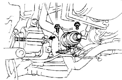
17. Turn away nuts and a bolt of fastening and remove the steering mechanism.
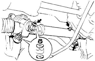
2WD
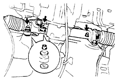
4WD
18. Turn away two nuts and disconnect a clip of a cable of management of automatic transmission.
19. From the transmission side, lower the power unit ten centimeters.
Attention: do not lower too low, so that the drive shaft does not come into contact with the suspension arm and damage the boots.
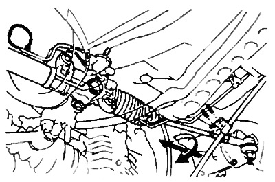
20. Disconnect the steering mechanism, turn it to the left and remove as shown in the figure.
Attention: when removing, wrap with rags those parts of the steering mechanism that may come into contact with the body to avoid damage.
Front steering gear (4WS).
1, 4 - fitting seat,
2, 11, 19, 32 - anther,
3 - worm body with control valve,
5 - rail guide,
6 - spring,
7 - guide rail cover,
8, 13, 25 - locknut,
9 - rear steering gear drive gear,
10, 28, 31, 36 - bearing,
12 - gear cover,
14, 17 - retaining ring,
15, 20, 37 - stuffing box,
16, 26 - spacer,
18 - restrictive sleeve,
21 - rail,
22, 33 - O-ring,
23, 35 - Teflon ring,
24 - threaded plug,
27 - bottom washer,
29 - top washer,
30 - steering gear housing,
34 - a worm with a control valve.
Note: when assembling, apply to the parts indicated by the arrows:
,
- grease,
- hydraulic booster fluid,
- sealant.
Steering rod replacement
1. Disconnect the tie rod ends from the steering knuckle arms.
2. Loosen the locknut and remove the tie rod end.
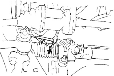
3. Remove steering draft.
A) Loosen the clamps and remove the tie rod cover.
Warning: Be careful not to damage the case.
b) Unbend the bent parts of the lock washer.
Attention: do not damage the rail.
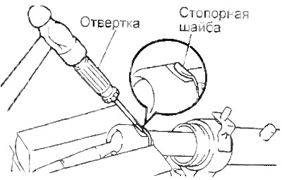
V) Turn away steering draft as it is shown in drawing Remove a lock washer.
4. Install a new tie rod.
A) Install a new lock washer.
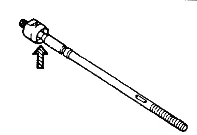
b) Apply grease to the tie rod ball joint (in the figure is indicated by an arrow).
V) Install and tighten the tie rod.
- Tightening torque - 85 Nm
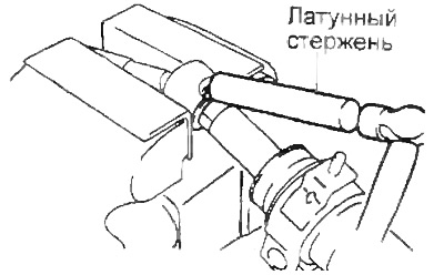
G) Using a brass rod and a hammer, bend the lock washer.
Attention: do not damage the rail.
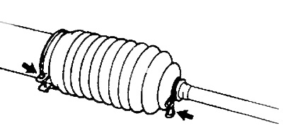
5. Install boot and clamps.
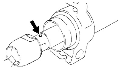
A) Make sure the hole in the rail is not clogged with grease.
Note: If the hole is clogged, the pressure generated inside the boot when the steering wheel is turned may damage the boot.
b) Install the cover and clamps Secure the cover with a large clamp.
6. Install the tie rod end.
A) Screw a counternut and a tip on steering draft.
- Tightening torque - 75 Nm
V) Make sure that the cover is not twisted and secure it with a small tie.
7. Connect the tie rod ends to the steering knuckle arms.
Attention: after replacing the steering rods, adjust the toe-in of the front wheels.
Installation
1. Install steering gear assembly.
A) Install washers on each steering gear stud on the right side.
b) Install the steering gear.
V) Install and tighten the steering gear nuts and bolt.
- Tightening torque - 60 Nm
G) (4WD Models)
Attach the transmission control cable clamp.
2. (4WD Models).
Install the engine mount.
A) Install the engine mount and tighten the bolt.
- Tightening torque - 89 Nm
b) Install the activated charcoal container.
- Tightening torque - 7.5 Nm
3. (4WD Models).
Install the air filter.
4. (4WD Models).
Install the front driveshaft.
A) Remove the mandrel.
b) Install the front driveshaft.
Note: Be careful not to damage the seal.
V) Align the alignment marks made during disassembly, install the mounting bolts and tighten them.
- Tightening torque - 75 Nm
5. Connect the intermediate shaft to the worm.
A) Install the intermediate shaft, aligning the marks made during disassembly.
b) tighten bolt (1) attaching the shaft to the worm.
- Tightening torque - 36 Nm
V) tighten bolt (2) attaching the shaft to the universal joint.
- Tightening torque - 36 Nm
6. Connect return and delivery pipelines to the steering mechanism.
- Tightening torque - 45 Nm
Note: Tighten the piping fittings so that no threads are visible.
7. Install the engine mount.
A) Install the engine mount bracket and tighten the mounting bolts.
- Tightening torque - 79 Nm
b) Install the support and tighten the bolt.
- Tightening torque - 89 Nm
8. Establish a longitudinal beam and tighten bolts and nuts of fastening.
Torque:
- Bolts A - 62 Nm
- Bolts B - 74 Nm
- Bolts C - 40 Nm
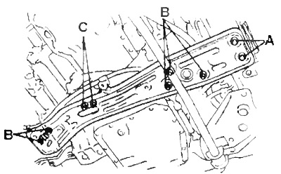
b) Install the holder and tighten the two bolts
- Tightening torque - 21 Nm
9. Install two bushings and two holders on the stabilizer and connect it to the body.
- Tightening torque - 86 Nm
10. Install the cross beam and tighten the mounting bolts and nuts.
Torque:
- Bolts A - 155 Nm
- Bolts B - 74 Nm
- Bolts C - 19 Nm
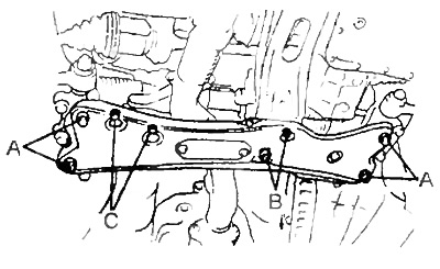
b) (automatic transmission)
Tighten the transmission control cable bracket bolts.
- Tightening torque - 4 Nm
11. Establish a reception pipe of the muffler.
12. Install the lower motor guard.
13. Connect the tie rod ends to the steering knuckle arms, tighten the nut and install a new cotter pin.
- Tightening torque - 50 Nm
Note: when installing the cotter pin, it is possible to turn the nut by an angle of not more than 60°.
14. Remove the engine support.
15. Install the front wheel
- Tightening torque - 105 Nm
16. Be convinced of correctness of installation of a steering wheel.
17. Top up the power steering fluid.
18. Bleed the power steering system.
19. Check for system leaks
20. Check the steering angles of the front wheels.
21. (4WD Models)
Check the transmission oil level.