Checking the level of hydraulic booster fluid
Note: The cooling system shares a reservoir with the power steering system.
1. Install the car on a flat horizontal platform.
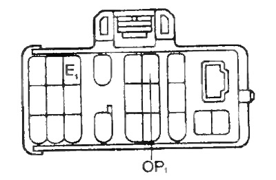
2. Short the leads "OR1" - "E1" diagnostic socket. Set the speed to 2000 rpm and warm up the working fluid.
- The temperature of the working fluid is 70-90°C
3. Verify that there is no foaming or emulsification of the liquid.
4. Measure the fluid level with the engine on and off.
- Maximum increase in liquid level - 5 mm
5. Check fluid level and top up if necessary.
Note: if the working fluid is warmed up, the fluid level is in the interval "NOT" on the tank or dipstick, if cold - in the interval "COLD".
Bleeding the power steering system
1. Check the fluid level in the tank
2. Raise the front of the vehicle and place it on stands.
Note: Be careful not to splash liquid out of the reservoir.
3. Start the engine and set the idle speed. Short the leads "OR1" - "E1" diagnostic connector, turn on the fan.
4. Turn off the engine.
5. Check for foaming or emulsification of the liquid. If foaming or emulsification is present, check for system leaks
6. Check fluid level.
Fluid Pressure Check
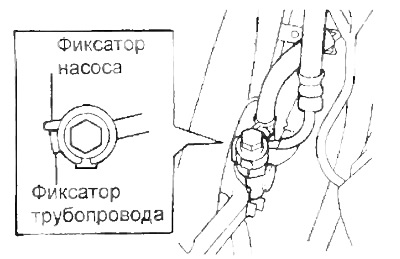
1. Disconnect the coolant pump discharge line.
2. Connect the pressure gauge as shown in the figure.
Attention: when connecting, the pressure gauge valve must be fully open.
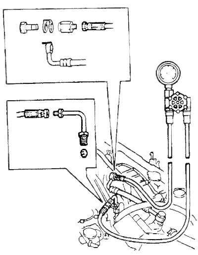
3. Rock the power steering system.
4. Check fluid pressure.
A) Short the leads "OR1" - "E1" diagnostic socket.
b) Measure the pressure of the working fluid at idle speed of the engine.
- System pressure — 1500-2800 kPa (At working fluid temperature 70 - 90°C)
V) Make sure the pressure drops when you remove the jumper «OR1» - «E1»
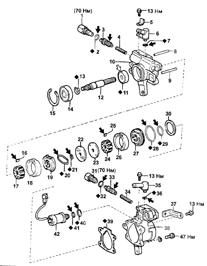
Power steering pump (ZS-T).
1, 31 - fitting of the discharge pipeline,
2, 7, 21, 28, 29, 32, 36, 40, 41 - O-ring,
3, 33 - flow regulator,
4, 34 - spring,
5 - holder,
6, 35 - fitting of the return pipeline,
8, 9 - pin,
10 - housing cover,
11 - stuffing box,
12 - pump shaft,
13.15 - retaining ring,
16, 25 - blade,
17, 24 - rotor,
18, 26 - stator ring,
19 - front disc,
20 - gasket,
22 - plate No. 1,
23 - plate number 2,
27 - rear disc,
30 - spacer,
37 - adjusting bracket,
38 - pump housing,
39 - gasket,
42 - solenoid valve.
Note: when assembling, apply to the parts indicated by the arrows:
- white arrow - grease,
- black arrow - hydraulic booster fluid.
Pump of the working fluid cooling system
Removing
1. Remove the lower engine guard.
2. Drain the coolant.
3. Remove a broad tank of a cooling liquid.
A) Disconnect the expansion tank hose.
b) Loosen the two bolts and remove the tank.
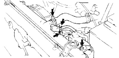
4. Disconnect the coolant inlet pipe from the radiator.
5. Disconnect the cooling system return line.
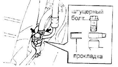
6. Turn away a union bolt and disconnect the delivery pipeline of system of cooling. Remove the gasket.
7. Remove the fan/pump assembly.
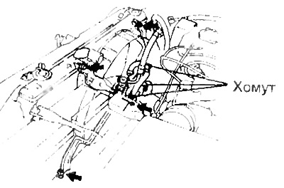
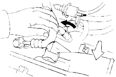
A) Disconnect the power steering fluid coolant pump return hose.
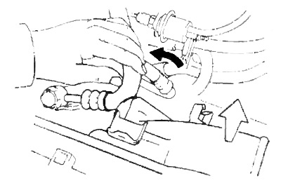
b) Loosen the four bolts and remove the fan assembly.
Note: bend the hose as shown.
8. Detach the protective cover from the fan.
9. Remove the fan.
Attention: the fan mounting nut has a left-hand thread.
10. Turn away three bolts and remove the pump of system of cooling of working liquid of the hydraulic booster.
Installation
1. Connect the pump to the fan mounting bracket.
- Tightening torque - 6.5 Nm
2. Connect the fan to the pump shaft.
- Tightening torque - 15 Nm
Attention: the fan mounting nut has a left-hand thread.
3. Connect the protective cover to the fan.
- Tightening torque - 5 Nm
4. Install the fan assembly.
Note: bend the hose as shown.
b) Tighten the four fan mounting bolts.
- Tightening torque - 5 Nm
V) Install a clamp on the return line.
5. Install a new gasket on the discharge line.
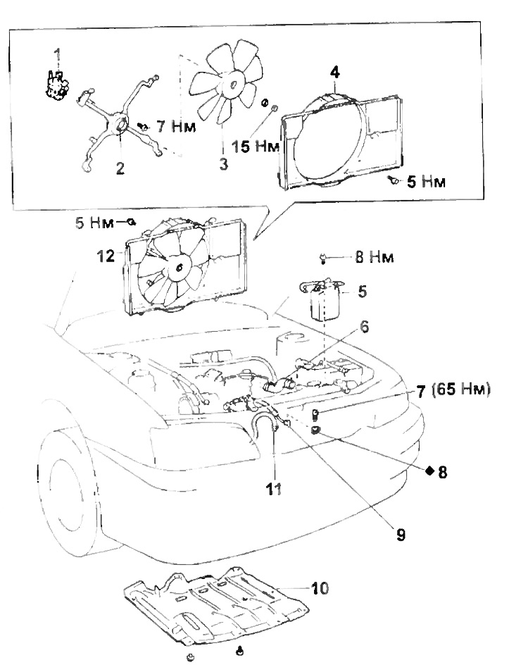
Removing the pump of the working fluid cooling system.
1 - pump,
2 - fan mounting bracket,
3 - fan,
4 - fan casing,
5 - expansion tank of coolant,
6 - coolant inlet pipe,
7 - nipple bolt,
8 - gasket,
9 - discharge pipeline of the working fluid cooling system,
10 - lower protective casing of the engine,
11 - return pipeline of the working fluid cooling system,
12 - fan assembly.
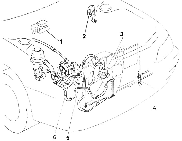
Power steering fluid cooling system.
1 - electronic air conditioner fan control unit,
2 - diagnostic connector,
3 - pump of the working fluid cooling system,
4 - air conditioner pressure switch,
5 - coolant temperature sensor,
6 - solenoid valve.
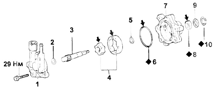
The pump of the cooling system of the working fluid.
1 - cover,
2, 5, 9 - spacer,
3 - pump shaft,
4 - driving and driven gear of the pump,
6 - ring seal,
7 - pump housing,
8 - stuffing box,
10 - retaining ring.
Note: when assembling, apply power steering fluid to the parts indicated by the arrows.
Connect the cooling system discharge pipe as shown in the figure. Tighten the socket bolt.
- Tightening torque - 65 Nm
6. Connect the return line of the cooling system.
7. Connect the coolant inlet.
8. Install the coolant expansion tank.
A) Install the tank and tighten the two bolts.
- Tightening torque - 7.5 Nm
b) Connect the expansion tank hose.
9. Fill with coolant
10. Fill in the power steering fluid.
11. Bleed the power steering system.
12. Check for coolant leaks.
13. Install the lower engine guard.
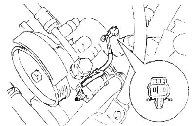
Checking the power steering pump solenoid valve
Using an ohmmeter, measure the resistance between the valve connector terminals.
- Resistance at 20°C - 7.6-6.0 Ohm
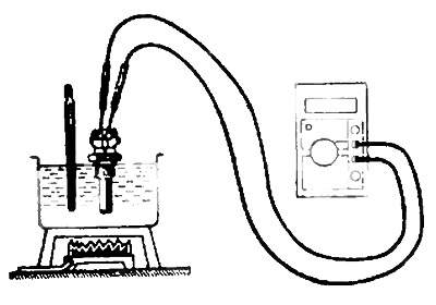
Check of the gauge of temperature of a cooling liquid Connect an ohmmeter and measure resistance between conclusions of the gauge as it is shown in drawing.
- Resistance at 80°C - 1.48 -1.58 kOhm
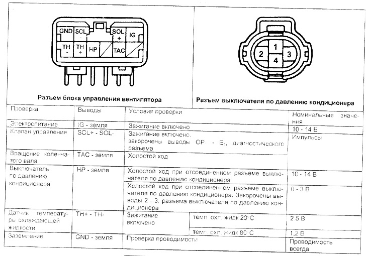
Checking on the connectors of the cooling fan control unit and the air conditioner pressure switch
1. Using a tester, measure the voltage between the terminals of the connectors of the cooling fan control unit and the air conditioning pressure switch.
2. Using an oscilloscope, check for pulses.
Attention: the check is made with the connector connected on its reverse side.
Table. Checking on the connectors of the fan control unit and the air conditioner pressure switch