Note: for specific operation of 4WS vehicles, see chapter "User manual".
Checking the operation of the 4WS system
1. Install the rear wheel on the turntables.
2. Jack up the front of the vehicle and place it on stands.
3. Apply the parking brake.
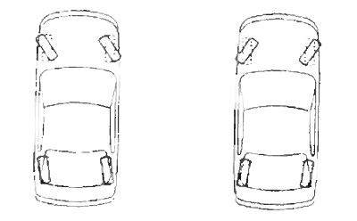
4. Check the direction of rotation of the rear wheels.
(Checking work on "small" speed) Turn the steering wheel to make sure the rear wheels turn in the opposite direction to the front wheels.
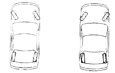
(Checking work on "big" speed)
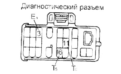
A) Short circuit the leads "E1"- "TS", "E1" -"TC" and turn on the ignition.
Attention: do not confuse the conclusions of the diagnostic connector when connecting.
b) Turn the steering wheel to make sure the rear and front wheels turn in the same direction.
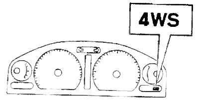
Checking the operation of the 4WS warning lamp
Turn on the ignition. The lamp should be on for two seconds and then turn off.
Troubleshooting
1. Check the connection of the connectors to the drive control unit 4WS.
2. Make sure that the voltage at the battery terminals with the engine off is 10-14 V.
3. Check the elements of the 4WS control system.
4. Checking the operation of the system in protected mode.
In the event that a problem occurs in the 4WS system, it goes into protected mode and the 4WS lamp lights up.
Note: when the ignition is turned off, the fault codes are reset.
Reading trouble codes
1. Make sure that the voltage at the battery terminals with the engine off is 10-14 V.
2. Reading fault codes.
A) Short the leads "TC" - "E1" diagnostic socket.
Attention do not confuse the leads when connecting.
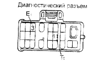
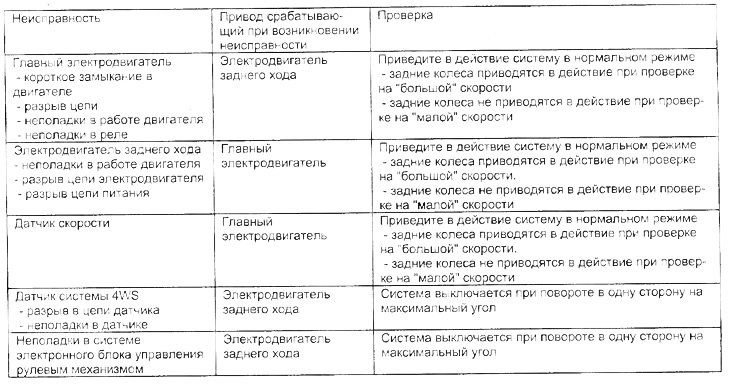
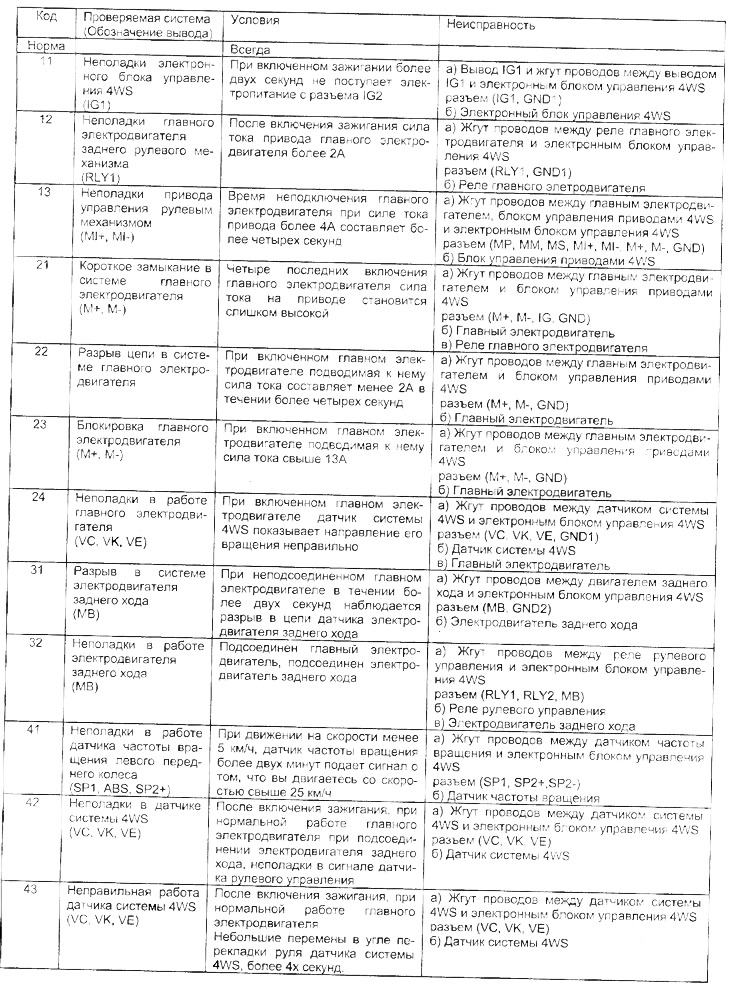
Table. System operation in the event of malfunctions
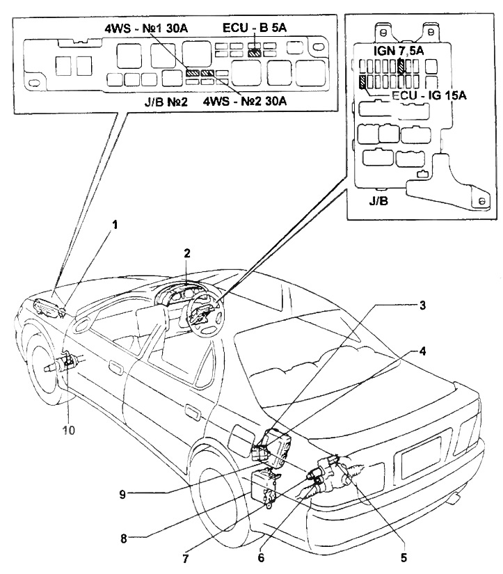
Location of elements of the 4WS system.
1 - diagnostic connector,
2 - speed sensor (instrument cluster),
3 - 4WS main motor relay,
4 - 4WS reverse motor relay,
5 - reverse motor,
6 - 4WS system sensor,
7 - main electric motor,
8 - electronic control unit 4WS,
9 - drive control unit 4WS,
10 - speed sensor.
b) Turn on the ignition.
V) Read fault codes by the number of flashes of the 4WS indicator lamp.
Note:
- If there is no fault, the 4WS warning lamp will flash at 0.25 second intervals.
- The fault code consists of two digits, the first of which is determined by the initial series of flashes of the 4WS warning lamp, then after a pause of 1.5 seconds, a second series of flashes follows, which corresponds to the second digit of the code.
- If there are two or more fault codes, the smallest code will be displayed first, and then the remaining codes in ascending order. There will be a 2.5 second pause between codes.
- After the output of all fault codes, a pause of 4 seconds follows, then the output of fault codes is repeated.
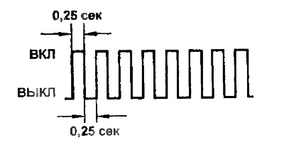 | 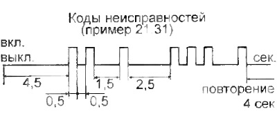 |
Table. Fault codes
Erasing diagnostic codes
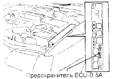
1. After troubleshooting, remove the ECU-B 5A fuse for more than 10 seconds, then install it back.
2. Verify that no fault code is displayed.
Setting the rear wheels in the direction of travel in a straight line
Installing by rotating the reverse motor
Note: installation is carried out with the ignition off.
1. Remove the trunk mat.
2. Remove a lateral facing of a luggage carrier.
3. Disconnect the reverse motor connector.
4. Set the rear wheels in the direction of travel in a straight line.
A) Turn the steering wheel to the extreme position.
b) Apply voltage from the battery to the reverse motor connector as shown.
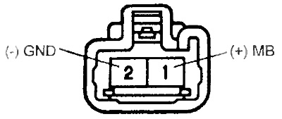
Attention: do not remove the terminals from the connector.
V) Stop the movement of the electric motor at the moment when the rear wheels are straight.
Note:
- If you applied voltage, but within five seconds the rear wheels did not start to turn, then install using a special tool (see below).
- Do not leave the battery connected after installation.
- Do not apply more voltage to the reverse motor connector than the battery voltage.
5. Connect the reverse motor connector
6. Establish lateral facing of a luggage carrier.
7. Install the trunk mat.
Installation with a special tool
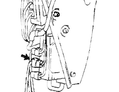
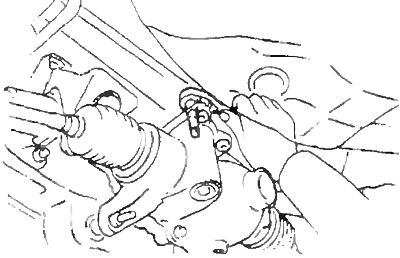
1. Turn away three bolts and remove a protective casing of conducting.
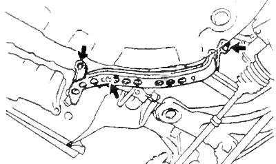
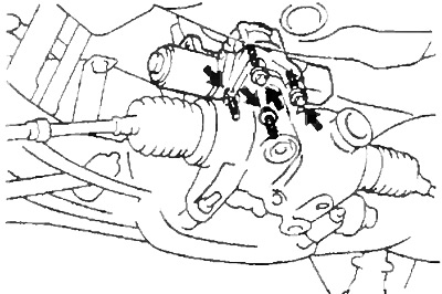
2. Turn away bolts and remove the electric drive of management of the steering mechanism in gathering. Remove the seal.
3. Using the special tool, turn the rear steering worm counterclockwise until the rear wheels are in the straight ahead direction.
4. Install the drive assembly.
A) Install a new seal on the power steering
Note: pre-clean the surfaces of the electric drive and the rear steering mechanism in contact with the seal.
b) Install the actuator assembly and tighten the four bolts.
- Tightening torque - 5 Nm
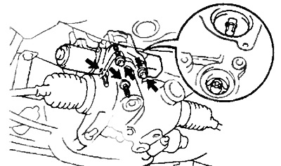
Note: there is a gap between the drive and the mechanism due to the seal.
5. Install the wiring guard.
When troubleshooting, please note:
- If it is necessary to disconnect one of the connectors during repair, first disconnect the main motor steering relay and reverse motor steering relay connector.
- The main motor/reverse steering relay connector is connected last and the 4WS system is tested after it is connected.
Checking 4WS System Components
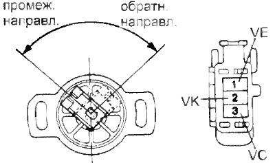
1. Check the 4WS system sensor.
A) Measure resistance between leads "VC" - "VE" sensor.
- Resistance - 5.25-9.75 kOhm
b) When you actuate the sensor lever, make sure that the resistance between the leads changes "VK" - "VE".
2. Check the speedometer (see the relevant section of the chapter "electrical equipment").
3. Check the front left wheel speed sensor (see the relevant section of the chapter "Brake system").
4. Check motor relays.
A) Check for continuity between the terminals:
- Main motor - IG1 - PLY 1
- Reverse Motor - IG2 - RLY2
b) Make sure there is no continuity between the terminals:
- Main motor - + B1 - IG
- Reverse motor - + B2 - MIG
V) Apply voltage to the terminals: (main motor - "IG1" - "RLY2", reverse motor - "IG2" - "RLY2") and make sure there is continuity between the pins:
- Main motor - + B1 - IG
- Reverse motor - + B2 - MIG
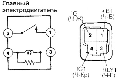 | 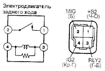 |
Note: in the figure, the colors of the wires are shown in parentheses (for decryption, see chapter "Electrical equipment diagrams").
5. Check the 4WS main motor.
Note: Do not disconnect the main motor from the rear steering gear.
A) Apply voltage to the main motor connector terminals and check for smooth operation.
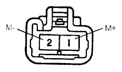
b) Reverse the polarity and check that the motor rotates in the opposite direction.
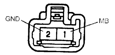
6. Check the reverse motor. Conclusion "MV" submit "+" battery, and to the conclusion "GND" submit
Make sure that the motor shaft rotates smoothly to the left when viewed from its end.
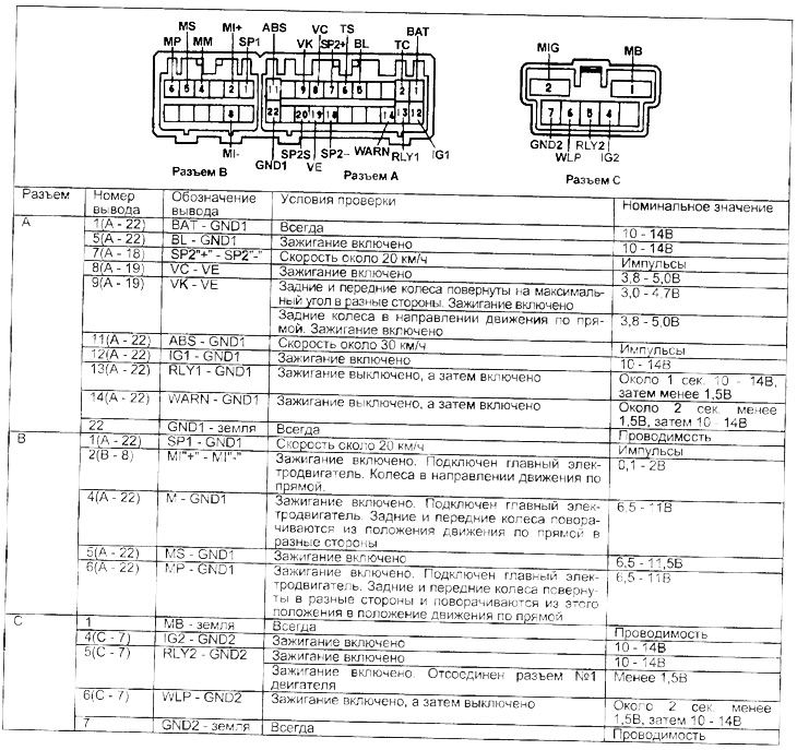
7. Check the 4WS electronic control unit.
Using a tester, measure the voltage and continuity between the terminals of the 4WS ECU connector. Note: the test is carried out with the connectors connected to the control unit on their reverse side.
Before measurements, check the power supply of the electronic unit and its "earth".
- With the ignition on, the voltage is 10 - 14V
- With the ignition off between "earth" and body resistance - less than 5 ohms
Table. Checking on the connectors of the 4WS electronic control unit