
Note: check and adjust the clearance in the valve drive on a cold engine.
Engines 3S-FE, 4S-FE
1. Remove throttle cable bracket (if it interferes with the removal of the cylinder head).
A) Disconnect the control cables from the throttle linkage.
b) Remove the two bolts and remove the accelerator cable mounting bracket.
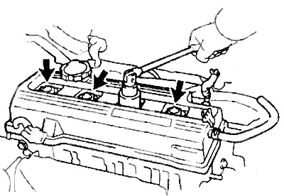
2. Remove the cylinder head cover.
A) Disconnect the four high voltage wires from the clamp on the cylinder head cover.
b) Disconnect the high voltage wires at the rubber caps. Do not pull high voltage wires.
Note: Pulling or bending the wires may cause internal damage.
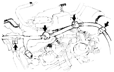
V) Disconnect the two crankcase ventilation hoses from the intake manifold and cylinder head cover.
G) Disconnect the power steering pump fluid return hose from the harness guard.
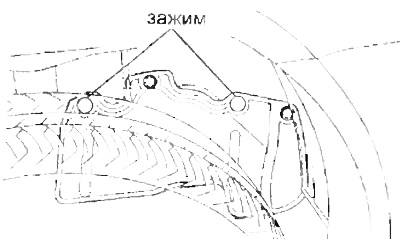
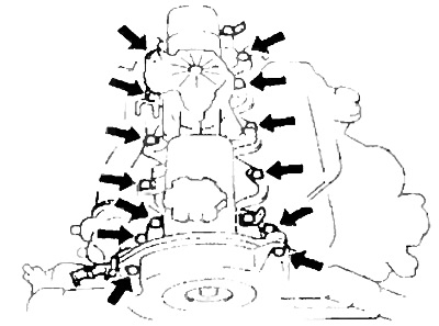
d) Remove the two wire harness protection clips from the timing belt cover No. 2 bolts in the sequence shown in the figure.

e) Remove four nuts, spark plug tube seal, cylinder head cover and gasket.
Note: Position the spark plug tube seals in the reverse order of removal to properly install them to minimize the possibility of oil leakage.
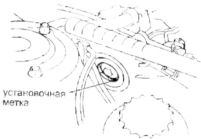
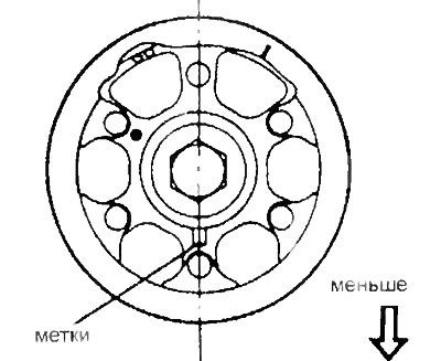
3. Set the piston of cylinder No. 1 to TDC of the compression stroke.
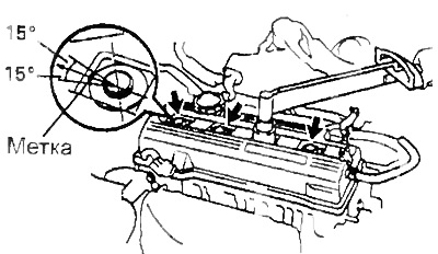
A) Rotate the crankshaft pulley and align its mark with the alignment mark "0" on the lower timing belt cover.
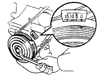
b) Check that the valve lifters for cylinder #1 are free and the valve lifters for cylinder #4 are tight.
If not, turn the crankshaft one turn (360°) and align the mark as above.
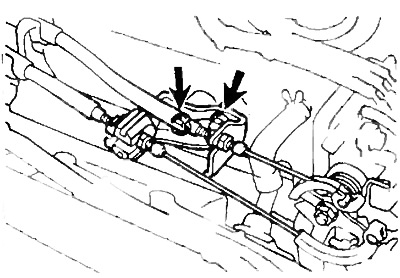
4. Check up a backlash in a drive of valves.
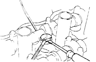
A) Check the clearance in the actuator of the valves indicated in the figure.
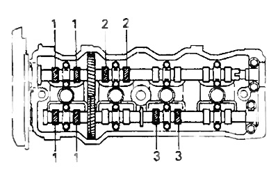
- Using a feeler gauge, measure the clearance between the tappet and camshaft.
- Write down the results - valve clearance measurements. These will be used later to determine the required shim when replacing.
Valve clearance (cold engine):
- intake - 0.19-0.29 mm
- graduation - 0.28 - 0.38 mm
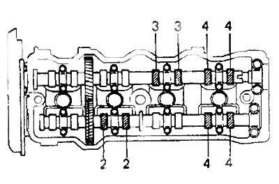
b) Rotate the crankshaft one revolution (360°) and align the labels as above.
V) Measure the clearance in the drive of the valves indicated in the figure.
5. Adjust the valve clearance.
A) Remove the adjusting washer.
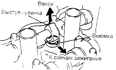
- Rotate the crankshaft so that the camshaft lobe is at the top.
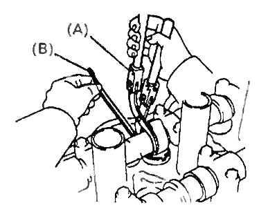
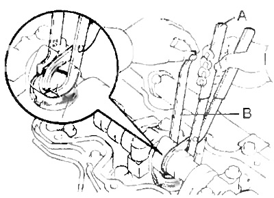
- Position the pusher as shown in the illustration.
Using a special tool (A), press the pusher, and place the special tool (IN) between the camshaft and pushrod.
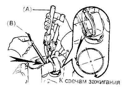
Remove special tool (A).
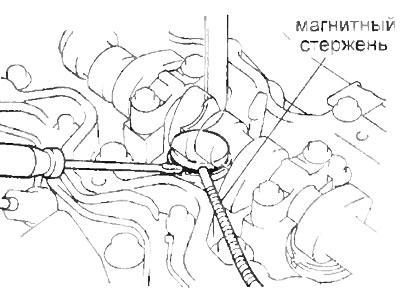
Remove the shim using a small screwdriver and a magnetic bar.
b) Determine the size of the new shim using the following method:
Using a micrometer, measure the thickness of the removed shim.
Calculate the thickness of the new shim so that the valve clearance is within the specified values.
The thickness of the removed adjusting washer - G
Measured valve clearance - A
New shim thickness - N
- inlet - N \u003d T + A (- 0.24 mm)
- graduation - N - T + A (- 0.33 mm)
Select a new shim with a thickness as close as possible to the design value.
Note: shims have 17 sizes (thickness values) from 2.50 mm to 3.30 mm through 0.05 mm.
V) Install a new shim into the tappet. Using a special tool (A), press the pusher, and remove the special tool (IN).
G) Recheck the valve clearance.
6. Install the cylinder head cover.
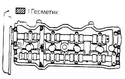
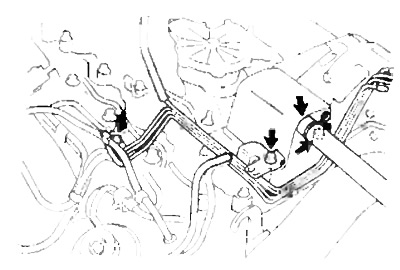
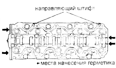
A) Remove the old sealing material and apply sealant to the cylinder head as shown.
b) Install the gasket on the cylinder head cover.
V) Install the cylinder head cover and four spark plug tube seals by tightening the nuts.
Tightening torque - 23 Nm
G) Install the engine wiring harness guard by tightening the two bolts securing the timing belt top cover in the reverse order of removal.
d) Install the power steering pump fluid return hose to the wire harness guard.
e) Connect the two crankcase ventilation hoses to the intake manifold and cylinder head cover.
and) Install the high voltage wires in the clamp on the cylinder head cover and connect them to the spark plugs.
h) Install two gaskets on the cylinder head cover
And) Install the cylinder head cover, washers and tighten the screws in several steps.
7. Install the throttle cable bracket by tightening the two bolts and connect the control cables to the throttle linkage.
ZS-T engine
1. Disconnect the accelerator cable
2. Remove the four clips and disconnect the wiring harness.
3. Disconnect two vacuum hoses
4. Disconnect the crankcase ventilation hose.
5. Turn away three bolts and move aside a vacuum tube aside.
Note: Do not disconnect the vacuum hose.
6. Turn away two bolts, remove two clips and separate a lateral protective cover from the right forward wing.
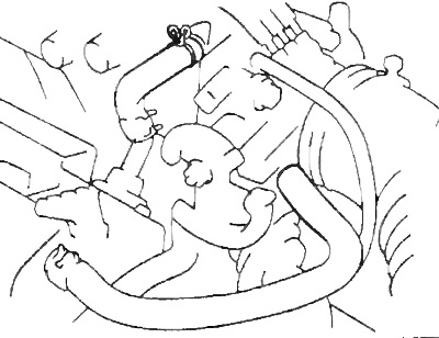
7. Remove the vacuum pump head cover
A) Remove the cover cap No. 2 of the timing belt.
b) Turn the crankshaft clockwise until the mark on the camshaft pulley is at the bottom.
In this position, the vacuum pump piston is at BDC and the spring compression becomes the smallest.
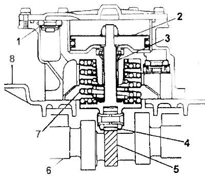
1 - safety valve,
2 - piston,
3 - stock,
4 - bearing,
5 - vacuum pump cam,
6 - camshaft,
7 - spring,
8 - block head cover.
V) Unscrew the two bolts of the cover No. 2 of the timing belt.
G) Loosen the wiring harness bolt.
d) Unscrew 10 bolts and remove the cover with the pump.
8. Measure backlashes in valves.
- Inlet - 0.20-0.30 mm
- Graduation - 0.25-0.35 mm
9. Adjustment of thermal gaps in valves.
A) Rotate the crankshaft so that the camshaft lobe is pointing up.
b) Position the notch in the valve lifter so that it faces the intake manifold.
V) Using a special tool (A), press down on the valve lifter and install the special tool (IN) between the camshaft and the valve lifter.
G) Using a small screwdriver and a magnetic bar, remove the old shim.
d) Measure the thickness of the removed shim with a micrometer. Calculate the thickness of the new shim so that the calculated gap satisfies the values given in the specifications:
- T - thickness of the removed washer, mm
- A - measured gap, mm
- N is the thickness of the new washer, mm
- Inlet valve - N \u003d T + [A - 0.25 mm]
- Exhaust valve - N \u003d T + [A - 0.30 mm]
Pick up an adjusting washer with a thickness closest to the calculated one.
Note: Shims come in 25 sizes: from 2.20mm to 3.40mm in 0.05mm increments. The thickness is stamped on the washer.
e) Install a new shim in the valve lifter.
and) Using a special tool (A), push down on the valve lifter and remove the tool (IN).
Check the valve clearance again.
10. Installation of a cover of a head of the block of cylinders in gathering with the vacuum pump.
A) Install the camshaft pulley with the mark down.
b) Remove any remaining old sealant.
V) Apply sealant to the cylinder head at the locations shown in the illustration.
G) Install the head cover with ten bolts.
- Tightening torque - 13.5 Nm
d) Tighten the wiring harness bolt.
e) Install and tighten the two #2 timing belt cover bolts.
Tightening torque - 7.5 Nm
11. Install the side protection cover on the right front fender, secure it with bolts and clips
12. Push the vacuum tube back into place. Tighten the three bolts.
Tightening torque - 7.5 Nm
13. Connect the crankcase ventilation hose.
14. Install the wiring harness and secure with four clips.
15. Connect two vacuum hoses.
16. Connect the accelerator cable.