
Typical ignition system of the cars in question
1. Camshaft rotation sensor; 2. Crankshaft rotation sensor; 3. Other sensors; 4. From the battery; 5. Ignition coil; 6. Candle
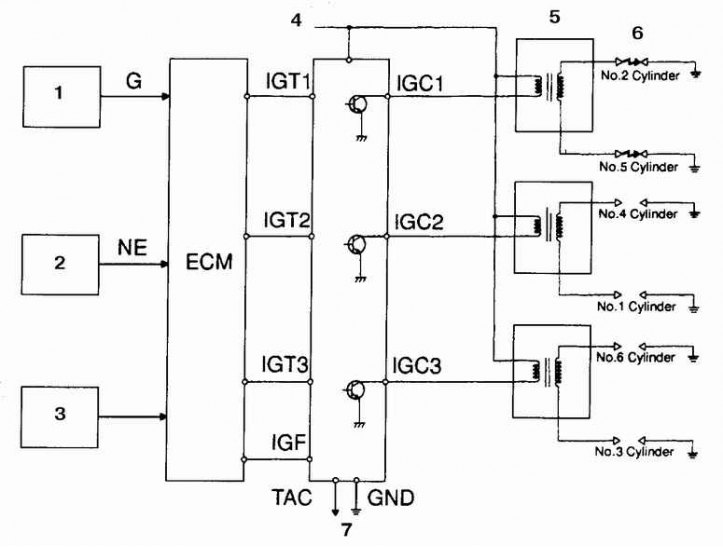
The vehicles in question are equipped with a distributorless ignition system (so-called. DIS system), in which one coil falls on two cylinders.
The DIS system uses dual spark ignition. A spark appears simultaneously in two cylinders, the piston of one performs a compression stroke, and the other - an exhaust stroke. Moreover, in the first of these cylinders, the power of the spark discharge is much higher than the power of the discharge in the second, in which the spark is used only for afterburning the remnants of the unburned combustible mixture. On V6 engines, the spark is created in pairs of cylinders 1-4, 2-5, 3-6, and in 4-cylinder engines - 1-4 and 3-2.
The DIS ignition system includes camshaft and crankshaft rotation sensors, a processor (PCM module), coils and electronic module. The processor generates identification signals for each cylinder, which trigger an electronic module that switches the ignition coils. The processor unit automatically adjusts the ignition timing in response to signals from various vehicle sensors. The electronic module distributes the signals to the respective coils and sets the delay time until the coil is switched in accordance with the current in the primary circuit.
On V6 engines, the left cylinder head spark plugs are inserted directly into the connectors on the coils, and the right cylinder head spark plugs are connected to the coils by wires. On 4-cylinder engines, the coils are mounted next to the cylinder head, the spark plugs are connected to the coils by wires. The electronic module is mounted on V6 engines next to the brake master cylinder, under the relay mounting block, on 4-cylinder engines, the module is integrally integrated into the coil housing and changes with them.
Attention! If the engine fails to start, do not leave the ignition on for more than 10 minutes.
Connect a tachometer in accordance with the manufacturer's instructions. Some tachometers are not compatible with the vehicle's electrical system. Before purchasing a tachometer, consult a car service.
Do not allow ignition coil leads to touch ground.
It is forbidden to disconnect the battery from the ground while the engine is running.
Always make sure that the electronic ignition unit is securely connected to ground.
Examination
If the engine does not start, and the starter rotates the crankshaft, then disconnect the wire from the spark plug of the left cylinder and connect it to a test gap. The arrester must be specially designed to test the DIS system.
Start the engine and check for spark.
If a spark is observed, then turn out the candles and check their condition.
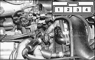
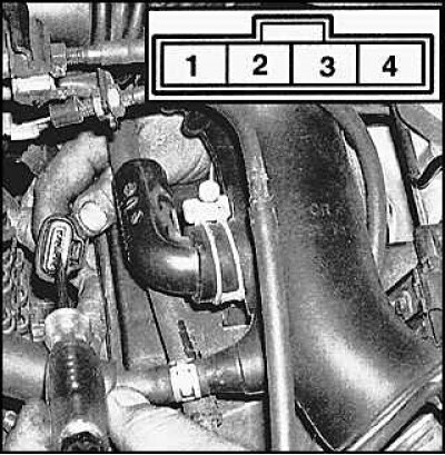
Attention! On a V6 engine, connect to the wires leading to the rear cylinder head to test.
If there is no spark, or sparking is intermittent, then check the battery voltage at each coil. If there is voltage, then check the resistance of the coil windings.
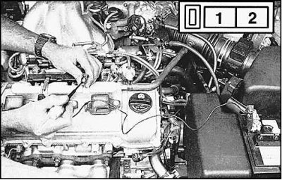
To check the coil voltage on a 4-cylinder engine, disconnect the connector, turn on the ignition and attach a voltmeter to terminal 1 of the connector (the test is carried out with the engine not running).
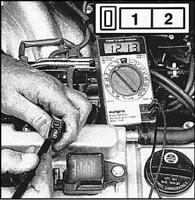
To check the voltage on the coil on the V6 engine, disconnect the connector, turn on the ignition and attach a voltmeter to terminal 1 of the connector (the test is carried out with the engine not running).
Check Shaft Rotation Sensors (see subsection 7.2.10., subsection 7.2.11.).
Check the signal from the processor on the coils (on a 4-cylinder engine) or from the electronic unit (on V6 engine).
To do this, on a 4-cylinder engine, check for 5V at terminal 3 of the coil connector with the ignition on.
Also check for a fluctuating 0.1-4.0V voltage at pin 2 of the connector (for this, the assistant must turn on the starter). If the voltage on the coil connectors does not meet these standards, then replace or repair the processor unit, otherwise replace the coil with the electronic unit.
On a 6-cylinder engine, the presence of a signal is checked by connecting a 12 V LED on pin 2 of the connector, which should flash when the starter is turned on. If there is no flashing, then check the electronic ignition unit (see subsection 3.4.8.).